
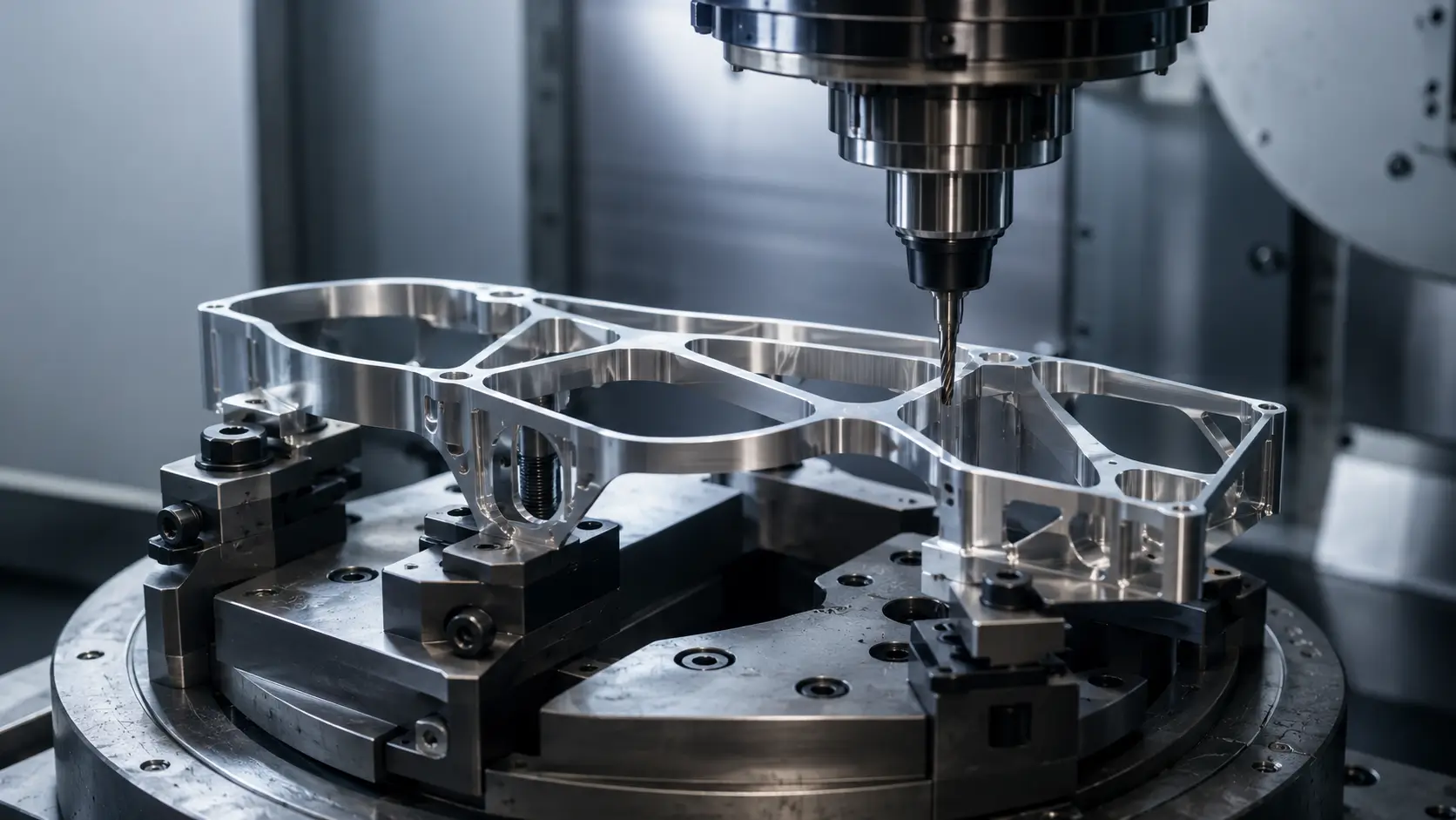
Controlling that behavior is a process question, not a design question. This article covers how thin-wall parts are actually machined without losing dimensional control, from workholding and cutting strategy through machining sequence and inspection. The mechanisms behind wall deflection and distortion are explained in the sections where they’re relevant, along with what an engineer running the job can do about each one.
What Makes a Thin Wall Difficult to Machine?
A wall becomes difficult to machine when it loses enough stiffness that cutting force, clamping force, or internal stress can move it by an amount that matters to tolerance or finish. Thickness alone doesn’t set that threshold. Wall height, unsupported length, surrounding geometry, how the part is held, and available tool access all shift where it actually sits.
The same nominal thickness can be routine in one part and high-risk in another. A short wall backed by solid material on two sides behaves like a much thicker, unsupported wall standing alone at height, even with an identical callout on the drawing. Thin-wall difficulty is a mechanical condition, not a number on a print.
Design-stage questions about how thin a wall can be specified for a given material, and what height-to-thickness proportions are reasonable to design around, are covered in CNC machining wall thickness guidelines. This article picks up once the wall has already been designed and focuses on what happens once it reaches the machine.
Why Thin Walls Deform During CNC Machining
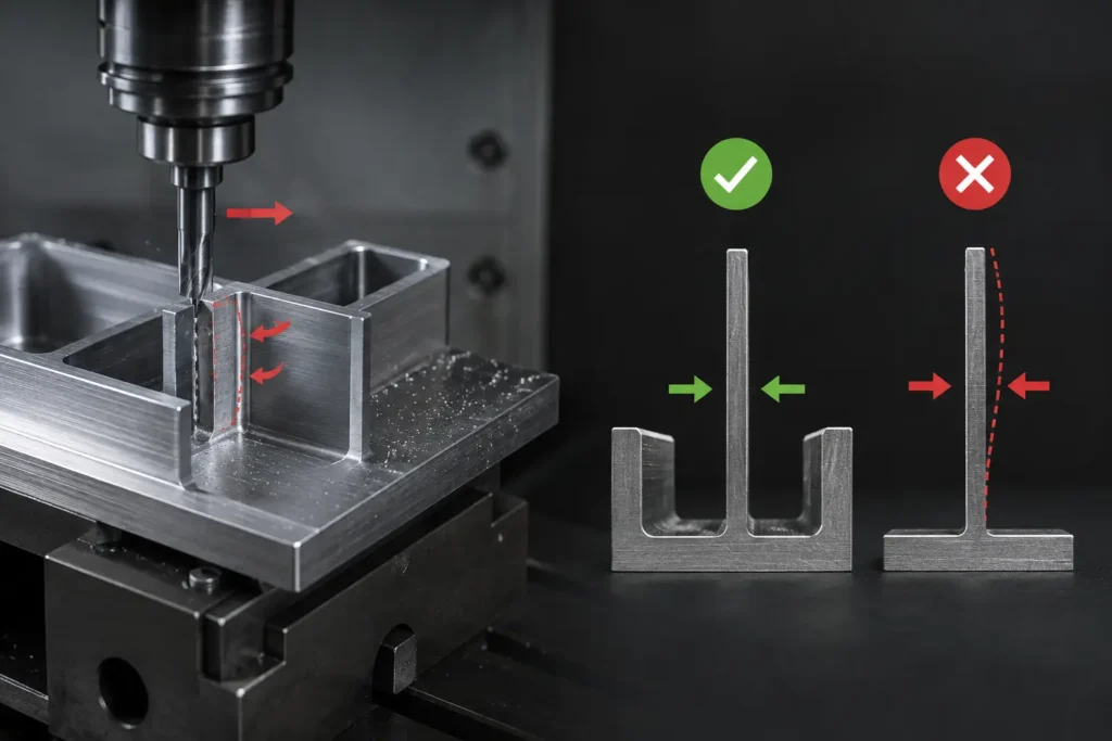
Thin-wall deformation isn’t one phenomenon with several names. Three distinct mechanisms are usually at work, and each calls for a different fix.
Cutting-Force-Induced Deflection
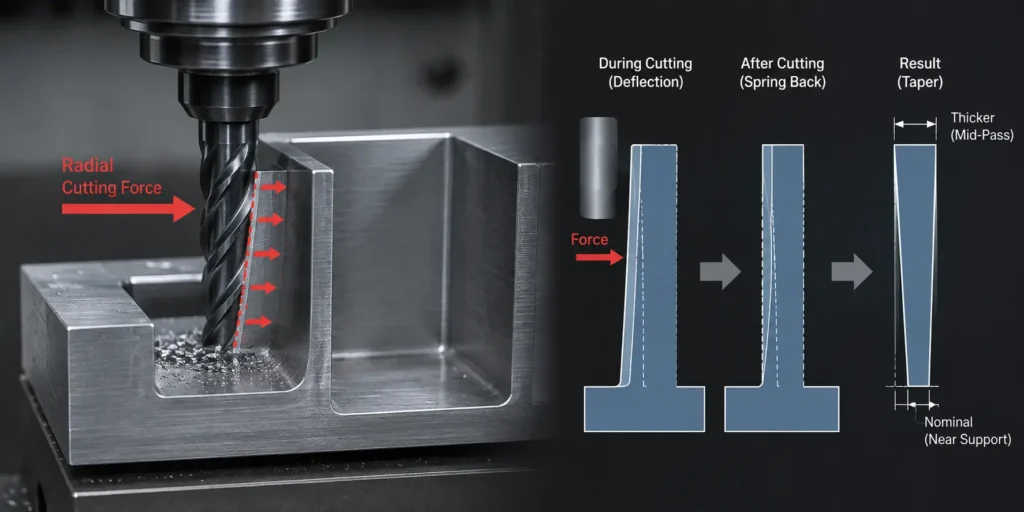
The radial component of cutting force pushes laterally against a thin wall as the cutter engages it. A rigid section barely moves; a thin one deflects away from the tool, changing the actual depth of cut versus what was programmed, then springs back once the load clears. What’s left is a wall that measures thicker mid-pass and closer to nominal near a supported edge, commonly called taper. Because this deflection tracks the applied load in real time, it changes as engagement, feed, or tool path change.
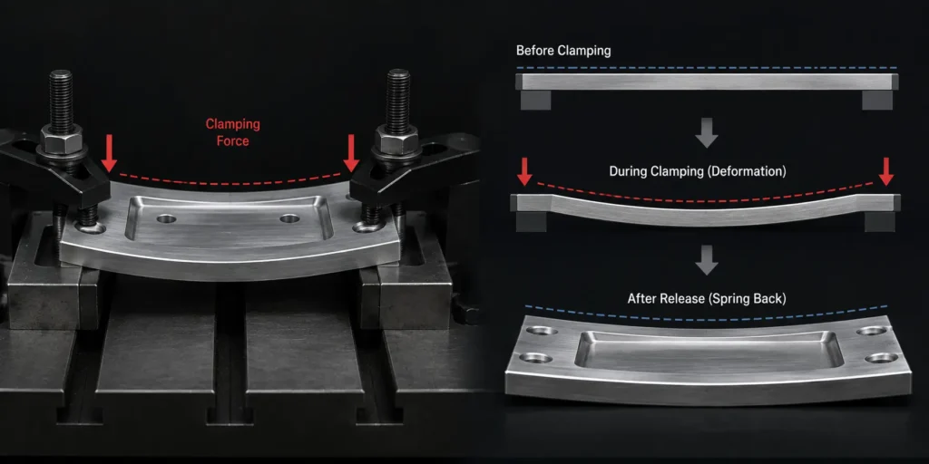
Workholding-Induced Deformation
A fixture can pull a flexible part out of its free-state shape before cutting even begins. Clamping pressure that’s uneven, or concentrated on a thin section, can bow or twist it under preload. The part then gets machined to a clean dimension while held in that distorted state, and the true geometry only shows up once the fixture releases it. This movement has nothing to do with the tool. It comes from how clamping load is distributed across the part.
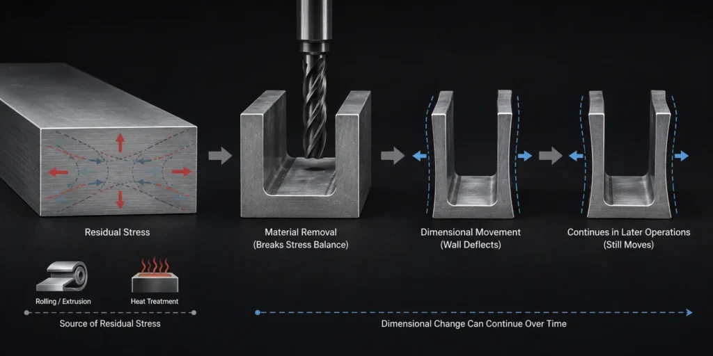
Residual-Stress-Related Dimensional Movement
Bar stock and plate material carry internal stress from rolling, extrusion, or prior heat treatment, held in equilibrium as long as the material stays intact. Removing material breaks that balance. A thin wall has less mass than a thick one to resist the resulting shift, so it shows the movement more readily as stock comes off around it. This isn’t triggered by the tool or the fixture. It can keep appearing as more material is removed in later operations, sometimes well after the feature that seems to be moving was itself already finished.
These three mechanisms often overlap in the same part, but they don’t respond to the same fix. A rib addresses deflection under cutting load. It does little for a wall distorted by uneven clamping, and nothing for movement driven by residual stress.
Workholding Strategies for Thin-Wall Parts
Workholding for a thin-wall part is a mechanical system, not a decision about how tightly to clamp. What matters is where support sits relative to the cutting zone, how the clamping load travels through the part, and how evenly it’s distributed across a section with limited stiffness of its own.
ZH Prototyping evaluates workholding case by case, since the right fixture approach depends on the part’s geometry and where deflection risk is actually concentrated. The company also holds patents for specialized fixture designs related to machining and workholding.
Clamping Force Trade-offs: Too Little vs. Too Much
Too little support and the part shifts or vibrates under cutting load, showing up as poor finish and inconsistent dimensions. Too much clamping force, or force concentrated in the wrong place, preloads the part into a distorted shape before the tool starts cutting, so it measures correctly while restrained and incorrectly once released. Neither direction is inherently safer. The right balance comes from the part’s stiffness, the fixture design, and where cutting loads actually land during the operation.
Soft Jaws, Custom Fixtures, and Localized Support
Soft jaws machined to a part’s actual contour spread clamping force over a larger area than hard jaws, reducing local pressure at any single contact point. Custom fixtures can add support directly behind a thin section, close to where cutting force is applied, limiting how far the wall can move under load. Vacuum workholding suits broad, relatively flat sections without needing mechanical clamping pressure at all, but it depends on surface condition and geometry, and it isn’t a substitute for mechanical support on features with complex shapes or limited contact area.
Temporary and Sacrificial Support
A wall can stay connected to surrounding stock through most of the roughing sequence, with final separation left until late in the process. Sacrificial webs or tabs tie a thin feature back to solid material during machining and get removed once the risk of deflection under heavy cutting loads has passed. The trade is more machining time and process planning in exchange for a more stable cut on the feature that actually needs it.
Toolpath and Cutting Strategy for Thin Walls
Cutting conditions set the mechanical load the workpiece has to resist. Radial engagement, axial depth of cut, step-over, and cutting direction all affect how much lateral force lands on a thin section at any given moment. A cutter’s rated maximum depth of cut describes what the tool can withstand, not what a flexible wall can tolerate without deflecting. Those are two different limits, and the tool’s capability doesn’t override the workpiece’s.
Climb vs. Conventional Milling
Climb and conventional milling apply cutting force in different directions relative to the tool’s rotation and feed. In some thin-wall conditions, climb milling directs force toward supported material rather than away from it, which can reduce deflection compared to conventional milling on the same setup. Cutter geometry, engagement, tool orientation, and how the part is supported all shape the actual force direction on the wall, so the choice gets evaluated against the specific setup rather than applied as a default.
Engagement, Depth of Cut, and Step-over
Reducing radial engagement lowers the lateral load on a thin wall during a pass, which can reduce deflection. How much reduction is actually needed comes down to the wall’s stiffness, the material, and how the part is held. Axial depth of cut and step-over work the same way: each trades cycle time for a smaller mechanical load, and the right combination is specific to the part rather than a fixed percentage carried over from job to job.
Roughing and Finishing Passes
Roughing removes bulk stock while more surrounding material is typically still in place to support the part. Finishing happens later, often after much of that supporting stock is gone, so the wall can be more flexible during finishing than it was during roughing, even though the cuts themselves are lighter. A light finishing pass isn’t automatically stable just because it removes less material. The finishing condition still has to be mechanically sound for the feature as it actually stands at that point in the process.
Tool Deflection and Tool Overhang in Thin-Wall Machining
Thin-wall cnc machining can involve two separate sources of flexibility at once, and they’re often discussed together in a way that blurs the line between them. Workpiece flexibility is a property of the part: a thin wall bends under load because there isn’t enough material to resist it. Tool-system flexibility is a property of the cutter, toolholder, spindle interface, and how far the tool reaches to get to the feature. A perfectly rigid workpiece can still produce a poor result if the tool system is deflecting or vibrating, and a very rigid tool can still leave a bad surface on a workpiece that’s moving under load.
Workpiece Flexibility vs. Tool System Flexibility
The distinction matters because the fix is different on each side. A wall deflecting because it’s thin calls for a change to workholding, cutting load, or machining sequence. A tool deflecting because it’s reaching deep into a pocket calls for a change to tool selection, holder rigidity, or approach strategy. Applying a workpiece-side fix to a tool-side problem, or the reverse, generally leaves the actual source of the error untouched.
Tool Overhang, Reach, and Holder Rigidity
Longer tool overhang increases sensitivity to deflection and vibration under the same cutting load, because the unsupported length of the tool acts like a lever arm between the cutting edge and where the tool is held. Shortening the overhang, stepping up to a larger-diameter tool where geometry allows it, or choosing a more rigid holder can improve stability in a deep or narrow feature. Overhang-to-diameter guidance varies by tool system, and tooling suppliers publish figures specific to their own products. Treat that guidance as supplier-specific rather than a general rule.
Machining Sequence for Thin-Wall Parts
The idea behind sequencing a thin-wall part is simple: preserve useful rigidity for as long as the process allows. Roughing generally happens while the structure still has more surrounding material intact, giving the part more inherent stiffness to resist cutting loads during the heaviest material removal. Retaining stock around a thin feature, or leaving temporary support in place, delays the point at which the feature becomes fully flexible.
Roughing While the Structure Is Still Rigid
Removing bulk stock while a thin feature is still backed by surrounding material puts the heaviest cutting loads on the part while it’s at its most rigid. Deflection risk during roughing doesn’t disappear, but it’s lower than roughing the same feature after it’s already isolated.
Retaining Stock and Temporary Support Until Late in the Process
Leaving extra stock, a sacrificial tab, or a temporary web in place until later operations keeps a thin feature tied to more rigid material longer, and that support comes out once the remaining operations no longer need it. Geometry, tool access, datum requirements, and fixturing all shape the actual sequence, and in some parts isolating the thin feature earlier is unavoidable regardless of the general preference to delay it.
Chatter Control in Thin-Wall CNC Machining
Chatter in thin-wall machining is a dynamic-system problem. The relevant system includes the machine, spindle, toolholder, tool, workpiece, and fixture together, and instability can originate in any of them. Slowing the spindle down is a common first response, but “RPM too high” rarely explains chatter on its own.
The Machine-Tool-Workpiece Dynamic System
Each component has its own stiffness and natural frequency, and the combined system can become unstable if the cutting process excites one of those frequencies. Excessive tool overhang, low workpiece stiffness, or a fixture that doesn’t adequately restrain the part can each contribute, and more than one factor is often present at once in a thin-wall setup.
Reducing Chatter Risk in Practice
Fixing chatter effectively starts with identifying which part of the system is contributing the most instability. Reducing tool overhang or increasing tool rigidity addresses a tool-side contribution. Improving fixture support or clamping distribution addresses a workpiece-side contribution. Adjusting engagement, depth of cut, or spindle speed changes the excitation the cutting process applies in the first place. The corrective action needs to match where the instability is actually coming from, not default to whichever adjustment is easiest to make.
Inspecting Thin-Wall Parts After Machining
Inspection is part of the thin-wall process, not a step that happens once the process is finished. A flexible part can measure correctly while restrained in a fixture and show a different geometry once that restraint is removed, because the fixture can be holding the part in a shape that isn’t its free-state condition.
Restrained vs. Free-State Measurement
Measuring a part while it’s still held in the fixture reflects the restrained condition. That’s useful for confirming a cut hit its programmed target, but it doesn’t necessarily represent how the part will measure once removed. Measuring after unclamping reflects the free-state condition, which is generally closer to how the part behaves in its intended application. Which condition actually matters comes down to how the part will be held or supported in use. ZH Prototyping’s inspection planning for thin-wall parts specifies up front whether a feature needs to be measured in-fixture, free-state, or both, based on the drawing requirement.
Why Parts Can Pass In-Fixture and Fail After Unclamping
A part machined under workholding-induced preload, or one carrying residual stress that hasn’t fully redistributed, can meet its dimensional targets while restrained and drift outside tolerance once released. This is a common source of parts that pass an in-process check and then fail final inspection, and it traces directly back to the deformation mechanisms already described rather than being a separate inspection problem.
Cost and Lead Time Impact of Thin-Wall Machining
Thin-wall machining adds cost through the specific process requirements it introduces, not through material or machine time alone. These additional requirements can increase the overall CNC machining cost, especially when the part needs custom workholding, temporary support, or additional inspection. Custom workholding takes engineering time to design and build before the first part is cut. Temporary or sacrificial support adds operations a simpler geometry wouldn’t need, and more conservative cutting conditions extend cycle time when deflection risk calls for them. Additional inspection, including free-state measurement where the drawing requires it, adds time beyond a standard dimensional check. These are process-development costs tied specifically to controlling a flexible feature, on top of whatever cost drivers apply to the part anyway.
Thin-Wall CNC Machining at ZH Prototyping
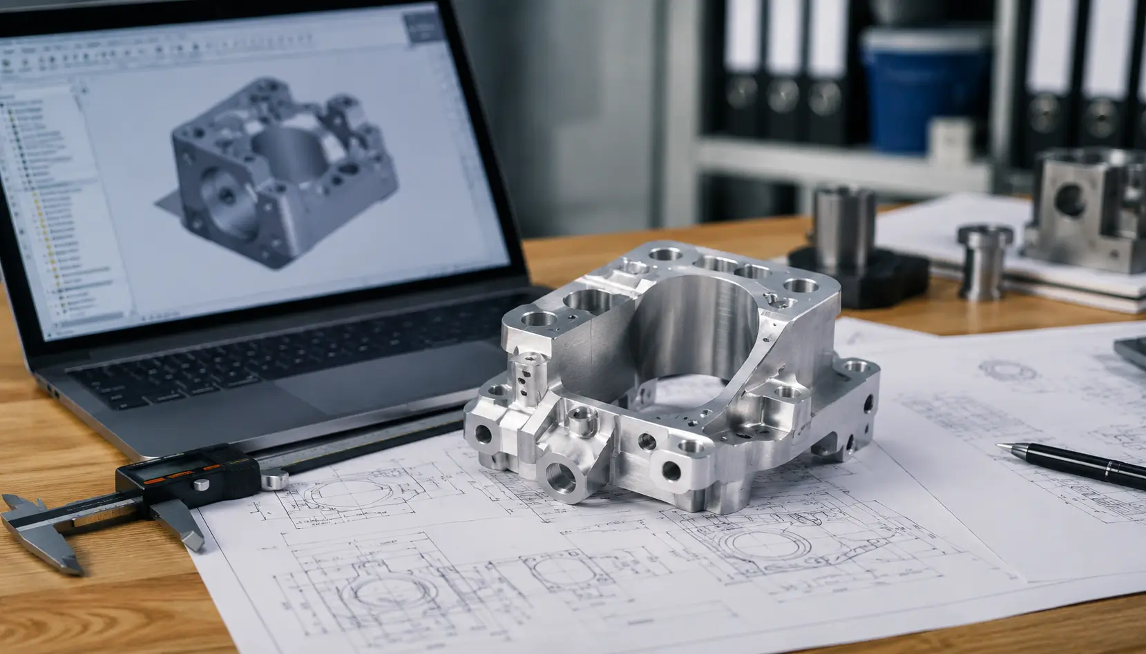
Thin-wall machining starts with understanding how the part will behave before material is removed. ZH Prototyping reviews part geometry, workholding requirements, tooling access, and machining sequence to identify potential deflection and distortion risks before production. Where the geometry requires additional support or specialized workholding, the machining process can be developed around the specific part rather than relying on a standard setup.
If you have a thin-wall component that requires tight dimensional control, send us your 3D CAD model and drawing for an engineering review and machining quote. Our team can evaluate the geometry, identify potential machining risks, and recommend a practical process before production begins.
FAQ
A wall is generally considered thin when its stiffness has dropped enough that cutting force, clamping force, or residual stress can move it by an amount that affects tolerance or finish. Wall height, unsupported length, surrounding geometry, and material set that threshold more than thickness alone, which is why the same nominal dimension can be routine in one part and high-risk in another.
There isn’t one fix, because thin-wall movement comes from more than one mechanism. Cutting-force deflection responds to workholding, cutting strategy, and machining sequence. Workholding-induced distortion responds to fixture design and clamping distribution. Residual-stress-related movement responds to material selection, stock condition, and in some cases stress-relief treatment, though whether that applies depends on the specific material and process route.
Climb milling can, in some setups, direct cutting force toward supported material rather than pulling the wall away from it, which may reduce deflection compared to conventional milling on the same part. It isn’t guaranteed in every case. Cutter geometry, engagement, tool orientation, and how the workpiece is supported all factor into which approach actually helps on a given setup.