
This guide walks through that full sequence: how die casting tooling gets built, what happens during a production run, and the trimming, secondary machining, surface finishing, and inspection steps that turn a raw casting into a finished part.
Die Casting Tooling Design and Construction
Every die casting run starts with the die itself, and the die is usually the largest single cost and the longest lead-time item in the entire project.
Die Casting Mold Components
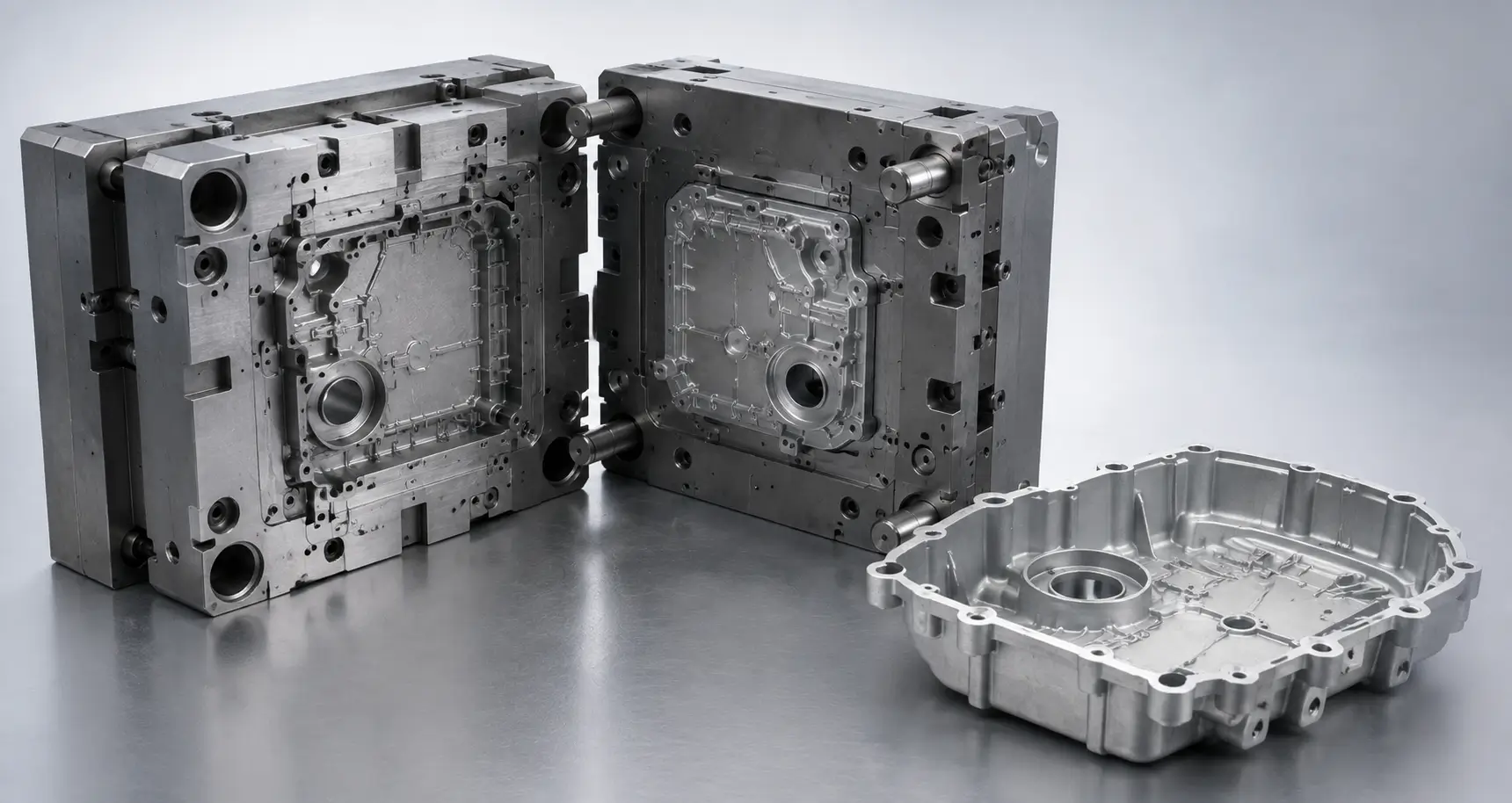
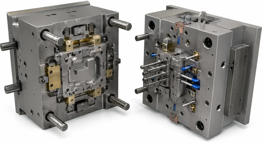
A production die casting mold is built from several functional components working together, not a single block of steel. The cavity and core define the part geometry, split across a fixed half mounted to the stationary side of the machine and a moving half that carries the ejector system. Slides and lifters handle any undercuts or side features that can’t be formed by the straight-pull motion of the two main halves. Cooling channels run through the die to control solidification rate, and the ejector system, pins, sleeves, or blades depending on the geometry, pushes the finished casting free once it has solidified enough to hold its shape.
Tool Steel Selection and Die Machining
Because the die is exposed to repeated cycles of high injection pressure and thermal shock, it’s machined from hardened tool steel, commonly H13 or an equivalent grade selected for resistance to thermal fatigue. Die construction typically follows a sequence: the cavity is rough machined close to final geometry, the steel is heat treated to reach its working hardness, and a finish machining pass brings the cavity to final dimension and surface finish once the steel is in its hardened state. Machining after heat treatment is necessary because the hardening process can introduce enough distortion that pre-hardened dimensions wouldn’t hold. During tooling design at ZH Precision, this heat-treat distortion is one of the reasons final cavity dimensions aren’t locked in until after the finish machining pass, not at the rough-machining stage.
Draft angle and shrinkage allowance are built into the die at this stage, and both depend on the alloy the die is designed for. Aluminum die casting tools typically need more draft than zinc, driven mainly by aluminum’s abrasiveness against the die surface rather than a large difference in shrinkage rate between the two alloys, which are broadly comparable. Magnesium die casting tooling carries its own allowances tied to the alloy’s shrinkage behavior and its reactivity during casting. A die designed for one alloy isn’t simply reused for another without reworking these allowances.
Die Casting Tooling Lead Time
Tooling lead time depends on part complexity, the number of cavities, and how much slide or lifter action the geometry requires, so it’s not a fixed number across projects. What is consistent is that tooling lead time is usually the longest single step in getting a new die casting part into production, which is why design changes get expensive and slow once a die is already in cut. Confirming geometry, tolerances, and material before committing to steel is what keeps that lead time from stacking with rework later.
Die Casting Production Steps, From Melt to Ejection
Once the die is qualified, production follows the same core sequence on every cycle:
- Melting and holding. Metal is melted and held at a controlled temperature, ready to be drawn into the injection system for each shot.
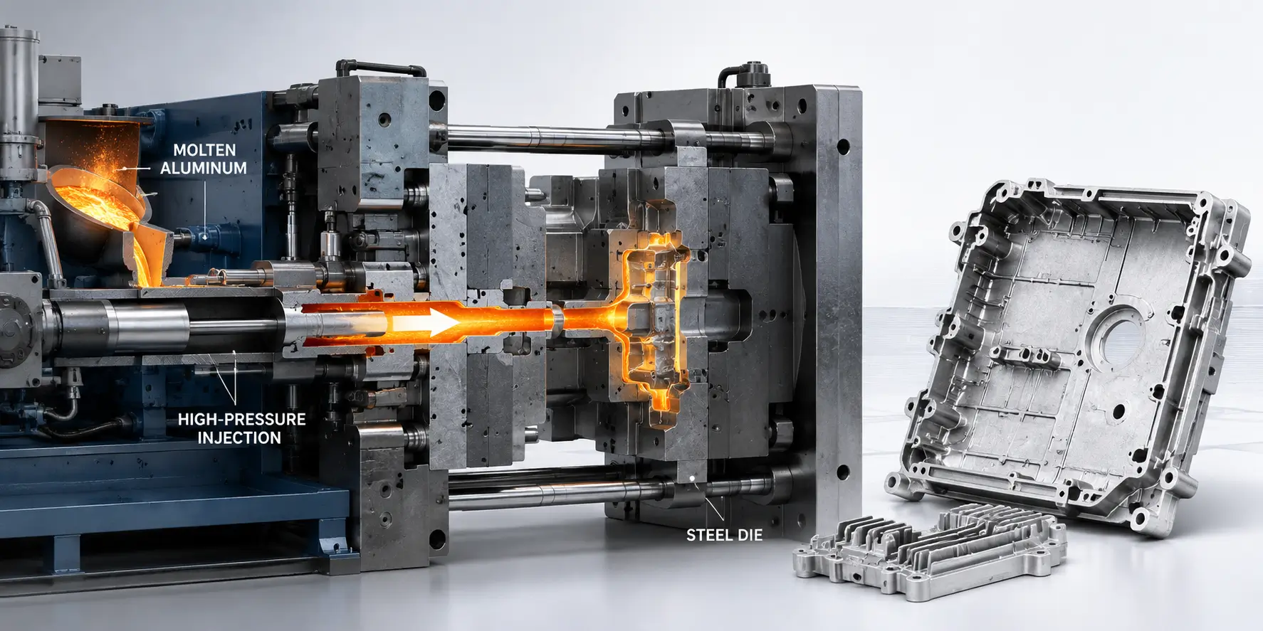
- Die closing and injection. In high pressure die casting, the two die halves close and clamp, then molten metal is injected into the cavity at high speed and pressure, filling the geometry before the metal front can cool and solidify prematurely.
- Intensification and solidification. Pressure is increased and held as the casting solidifies, feeding additional metal into the cavity to offset shrinkage as it cools.
- Ejection. The die opens and ejector pins push the finished casting free, ready to move on to trimming.
Trimming and Deburring After Die Casting
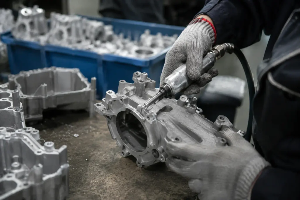
A part straight out of the die isn’t finished geometry. It’s still attached to the biscuit, runners, and any overflow wells that were part of how the cavity filled, along with a thin line of flash where metal escaped slightly at the parting line or around moving die components. Trimming removes the biscuit, runners, and overflows, most often in a dedicated trim press built to match the casting’s exact profile, so the excess material shears off in a single stroke rather than through manual cutting.
Deburring follows to remove the finer flash left along parting lines and around ejector pin marks. Depending on the part, this is done by tumbling, bead blasting, or hand finishing on features a trim die can’t reach cleanly. The material removed in both steps is typically clean enough to be remelted and reused as raw material, which is part of why die casting scrap rates matter less to overall cost than they would in a process without that recovery loop.
Secondary Operations and Surface Finishing
Not every feature on a die cast part comes off the trim press ready for assembly. Which secondary operations a part needs depends on what the feature is doing, not on a blanket rule for the whole part.
CNC Machining of Critical Features
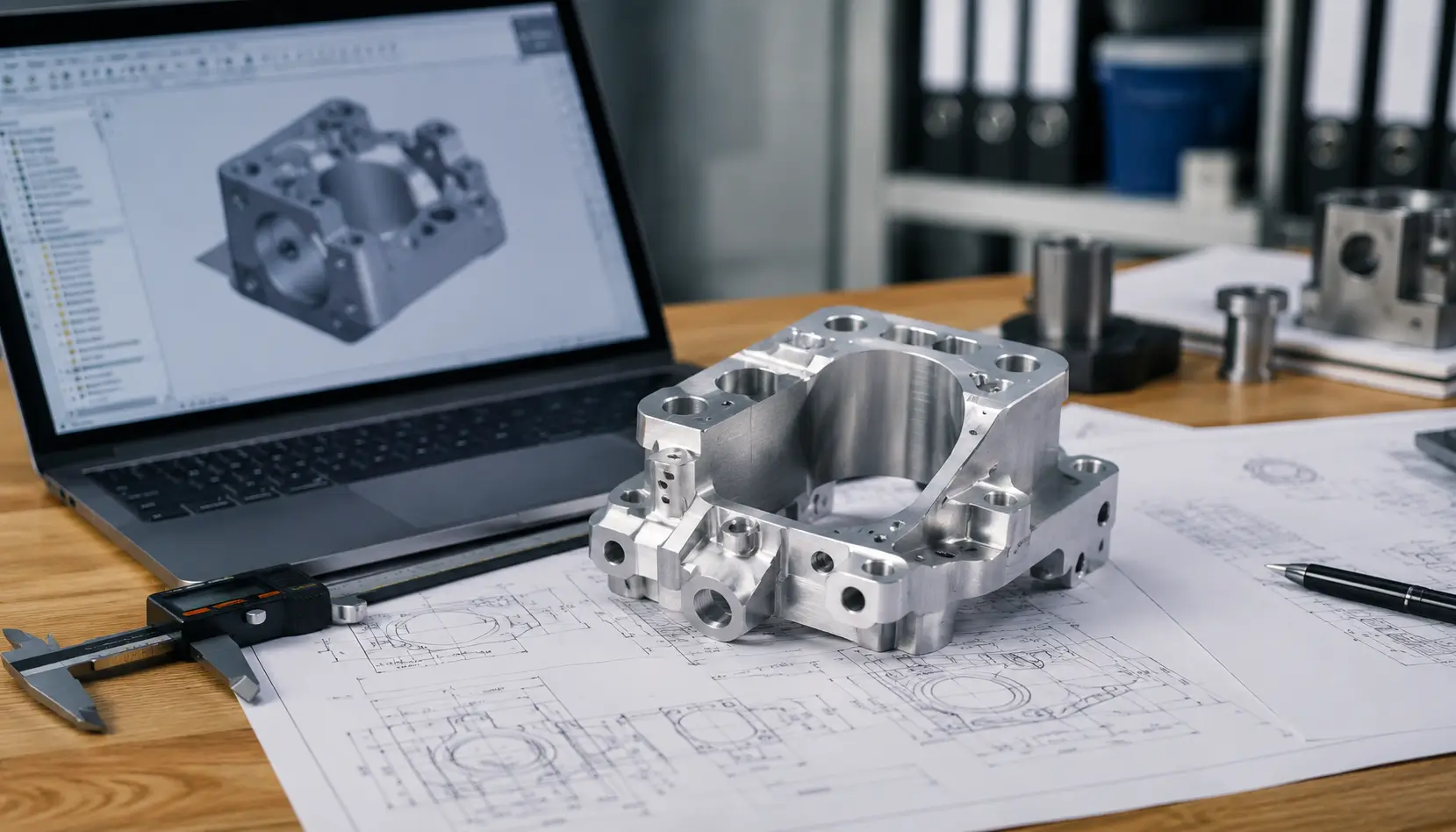
As-cast tolerances are good relative to sand or gravity casting, but features like threaded holes, sealing surfaces, or precision bores usually still need CNC machining after casting to hit their final tolerance. Casting the part net or near-net and machining only the features that need tighter control keeps the added machining cost proportional to what the design actually requires, rather than machining the whole part as if it started as solid stock.
For parts that could be produced by either process, the choice between CNC machining vs die casting depends on production volume, geometry, tooling cost, tolerance requirements, and how much secondary machining the casting will still require.
Surface Treatments for Die Cast Parts
Surface treatment requirements vary by alloy and by what the finish needs to do. Anodizing is common on aluminum parts for corrosion resistance and wear performance and adds a hard oxide layer that has to be accounted for on any toleranced dimension it affects. Zinc parts are often plated for corrosion protection and appearance, since zinc’s own corrosion resistance is more limited than aluminum’s in some environments. Magnesium parts generally need a protective coating, such as a chromate conversion coating or an e-coat layer, applied soon after casting, since magnesium is more reactive and corrodes more readily than aluminum or zinc if left untreated. Powder coating and painting are used across alloys where the requirement is primarily cosmetic or where a heavier protective layer is acceptable. As with machining, the finish should be tied to what it’s accomplishing on that specific part rather than applied as a default step.
Inspection and Quality Control in Die Casting
Inspection on a die cast part usually starts with a visual check for surface defects such as flash, cold shuts, or visible porosity, since these are often caught before dimensional inspection even begins.
Dimensional inspection follows, typically against the features called out as critical on the drawing rather than a full check of every dimension on the part. For fit-critical features, this can mean a CMM report or a dedicated gauge built for that feature; for cosmetic or non-critical dimensions, a general tolerance check is usually enough. Where a project requires a material certificate, certificate of conformance, or first article inspection, that documentation should be specified up front, since it affects how the inspection plan is built around the part rather than added after the fact. Inspection planning at ZH Precision generally starts from the drawing’s flagged critical features rather than a uniform inspection level applied to the whole part.
Die Casting Cycle Time and Production Rate
Cycle time in die casting is short by design. Once a die is in production, smaller parts commonly cycle in well under a minute, with larger or more complex castings running longer due to the added cooling time thicker sections need. Cycle time is set largely by how quickly the casting can solidify enough to eject safely, which ties directly back to wall thickness and cooling channel design decided during tooling. A die designed with cooling in mind from the start typically holds a faster, more consistent cycle time over its production life than one where cooling was an afterthought.
How to Choose the Right Die Casting Manufacturer
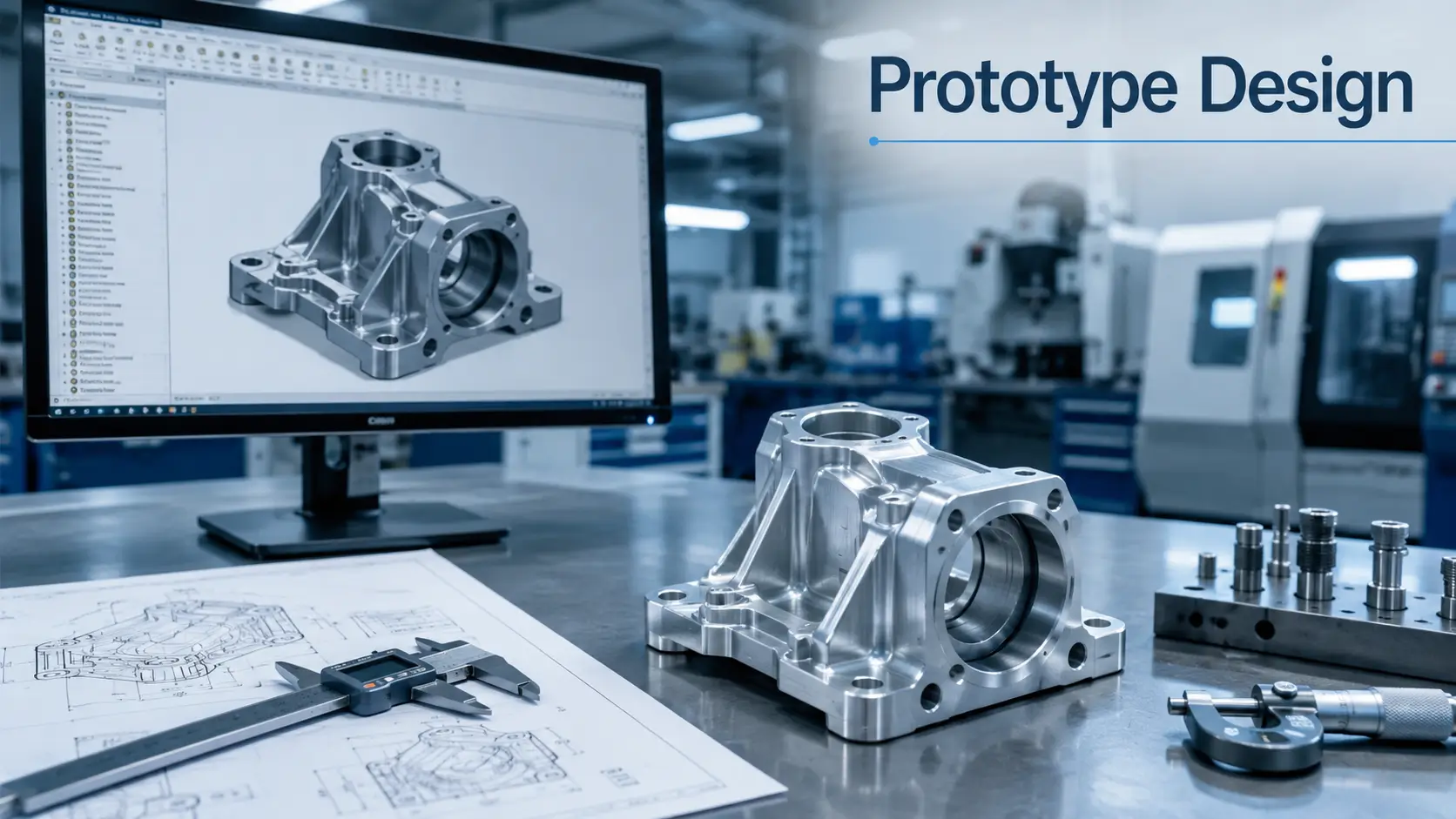
A reliable die casting manufacturer should review more than the drawing itself. Before tooling begins, the supplier should evaluate the part geometry, alloy, draft, parting line, wall thickness, tolerances, machining allowances, and surface requirements to identify manufacturing risks early and avoid unnecessary tooling changes or secondary operations.
ZH Prototyping supports die casting projects from DFM review and tooling through casting, CNC machining, surface finishing, and inspection. If you are planning a new die casting project, send us your 3D CAD model, drawing, alloy, quantity, and surface requirements. Our team will review your requirements and recommend a suitable manufacturing approach.
FAQ
Tooling lead time depends on part complexity, cavity count, and how much slide or lifter action the design requires, so there’s no single standard timeline. It’s typically the longest single step in bringing a new die cast part into production, which is why confirming geometry and material before cutting steel matters more than it would in a process with shorter tooling lead times.
The part is trimmed to remove the biscuit, runners, and overflows, then deburred to clean up flash along parting lines. From there, it may go through CNC machining for critical features, surface treatment such as anodizing or plating, and dimensional inspection before it’s considered a finished part.
No. Only features that need tighter tolerance than the as-cast dimension can reliably hold, such as threaded holes, sealing surfaces, or precision bores, typically require secondary machining. Which features those are should be specified on the drawing rather than left for the supplier to assume.