
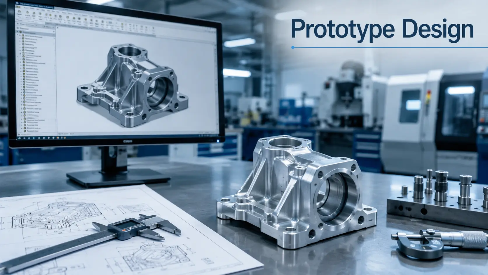
A prototype doesn’t need to reproduce every detail of the production part. It needs to reproduce whatever the current test is actually measuring: the geometry, material behavior, stiffness, load path, thermal response, sealing condition, or dimensional relationship the validation depends on. Everything else can be simplified, adjusted, or left flexible without consequence. Prototype design, in practice, is the work of deciding which differences from production are safe to carry and which ones will quietly change the result.
CNC Prototype Design vs. Production Design
A production part is designed to be made the same way many times. A prototype is designed to answer a question once or a few times while the design is still moving. That difference in purpose changes which manufacturing investments make sense.
Dedicated fixturing, process-specific geometry, and tightly controlled tolerances earn their cost in production because thousands of identical parts absorb the setup and programming investment behind them. A prototype rarely has that volume to spread the cost across. The same investment that pays for itself in production can be pure overhead on a part that might not exist in its current form next week.
This is why a prototype can reasonably use a general-purpose setup, a substitute material, or a simplified feature that a production engineer would never sign off on.
None of that means the prototype gets to ignore manufacturability, and it doesn’t mean every simplification is free. A feature can only be simplified for machining convenience if that simplification doesn’t touch what the current build is supposed to prove. A rib removed because it complicates a fixture is a reasonable trade if the test is checking bolt-pattern alignment. The same removal on a part being measured for deflection under load changes the structure being tested, not just the machining plan.
What Does Your CNC Prototype Need to Validate?
Treating every CNC prototype as one category is where most of the wrong assumptions start. A part built to check whether two components fit together has almost nothing in common, design-wise, with a part built to measure how it deforms under load, even if the CAD model is identical.
Fit and Assembly Prototypes
When the question is whether things go together correctly, the geometry that matters is mating interfaces, hole locations, alignment features, clearances, and assembly access.
A housing checked against a mating bracket needs its bolt pattern and external envelope to be accurate. The internal geometry that has no bearing on that fit can be built however is fastest to machine. Material properties matter far less here, because nothing about a fit check depends on stiffness or strength, unless the fit itself is affected by deflection under assembly force.
Functional Prototypes
When the question is how the part behaves under load, heat, or motion, the requirements invert.
Stiffness, strength, load path, deflection, thermal response, sealing, wear, and bearing or threaded interfaces become the things the prototype has to get right. Changing any of them changes the physical system being measured. A part that looks identical to production but was machined from a different alloy, or is missing a structural rib, isn’t testing the production design anymore. It’s testing a different mechanical system that happens to share a silhouette with it.
Appearance and Ergonomic Prototypes
When the question is how the part looks or fits within an assembly envelope, internal geometry that doesn’t touch the visible surface, the packaging envelope, or mass distribution can be simplified freely.
What has to be accurate is whatever a person or another component will actually see, touch, or need to clear.
Establishing which of these a build is actually for, before deciding on material, tolerance, geometry, or fixturing, is what keeps every decision that follows from being arbitrary.
Designing for Iteration in CNC Prototypes
Prototype geometry is rarely final on the first pass. Part of designing a prototype well is deciding where to leave room for that.
A mounting interface that hasn’t been checked against its mating part yet, a hole pattern likely to shift once assembly testing starts, or a bracket built to be swapped out between iterations are all reasonable places to build in adjustability. The geometry there is still genuinely undecided.
The mistake is treating flexibility as free. If the feature being made adjustable is part of what the current test is measuring, the adjustability itself becomes the confound. A slotted hole on an interface whose final position is still unknown preserves useful uncertainty. The same slotting applied to a bearing bore being evaluated for fit and load transfer changes the fit and load transfer. The prototype is no longer measuring the condition it was built to measure.
The question worth asking before adding any adjustable feature isn’t whether flexibility is good practice in general. It’s whether this particular flexibility helps the team learn something, or quietly changes the thing they’re trying to learn about.
When Does CNC Prototype Geometry Need to Match Production?
The geometry question and the flexibility question look similar, but they aren’t the same one. Flexibility is about what’s still undecided. This is about what has to be physically accurate regardless of whether it’s decided, because the test depends on it.
Geometry That Should Match Production
Geometry that affects stiffness, strength, load transfer, deflection, mating, alignment, sealing, thermal conduction, motion, bearing support, or fastener behavior generally needs to represent the production design closely. These are mechanical properties that geometry itself determines.
Remove an internal rib to simplify a fixture setup, and the local section stiffness changes. That changes how the housing deforms under load. That, in turn, changes how a shaft or bearing seated in it aligns, which changes the functional behavior actually being measured. The prototype can end up failing for a reason that doesn’t exist in the production geometry. It can also pass because a temporary solid section made it stiffer than the real part will ever be. Either way, the test result no longer describes the design it was supposed to describe.
Geometry You Can Simplify
Geometry that’s purely cosmetic, specific to a different manufacturing process, or simply irrelevant to the current question is a legitimate place to simplify.
A part destined for die casting but prototyped from billet doesn’t need its draft angles or parting-line features reproduced, if the build is only checking envelope and mounting fit. But if the build is evaluating how a rib shaped by that casting geometry behaves structurally, removing it removes the thing being tested.
The governing question is the same one from the last two sections, applied at the feature level: does this geometry affect the result, or doesn’t it. Feature-level rules for wall thickness, radii, and pocket depth belong in the dedicated CNC DFM material rather than repeated here. The point of this section is the filter, not the rule list.
How to Choose Materials for CNC Prototypes
Defaulting to “always match production material” skips the actual engineering question. Defaulting to “use whatever machines easiest” skips it in the other direction. The material only matters as much as the property it contributes to the current test.
Elastic modulus, yield strength, density, thermal conductivity, thermal expansion, wear resistance, corrosion behavior, and thread or bearing strength are all material-intrinsic. A part built to check whether it fits inside an envelope doesn’t depend on any of them, so a substitute material that machines faster or costs less is a legitimate choice.
A part built to confirm structural margin depends directly on stiffness and strength, and swapping alloys there changes the answer the test produces, not just the machining time. A housing evaluated for thermal performance depends on conductivity in a way an envelope check never will. The same substitution that was harmless for the fit check becomes the reason the thermal test can’t be trusted.
Regulated development adds a layer beyond this reasoning. In fields like medical devices, material and process fidelity can be governed by explicit requirements rather than left to engineering judgment alone. The substitution decision isn’t purely a cost-versus-risk call in those contexts. It may not be a call at all.
How to Set Tolerances for CNC Prototypes
A tolerance exists to keep manufacturing variation from being mistaken for a design result, or from hiding one. That’s the standard worth applying to a prototype print, rather than a blanket decision to tighten or loosen everything.
Features That Need Tighter Tolerances
Mating interfaces, locating datums, bearing and shaft fits, critical hole patterns, sealing interfaces, and alignment features are the places where dimensional variation can directly change what the test measures. This is where tight control earns its cost.
A critical interface left on a general tolerance can introduce enough part-to-part variation that the engineer can no longer tell whether a test result reflects the design, or reflects the specific part that happened to get measured.
Features That Can Use General Tolerances
Tightening dimensions that don’t touch the validation adds machining operations, more careful setup, and more inspection time. None of that makes the result any more trustworthy. It just slows the iteration down for no engineering benefit.
Both directions cost something. Matching tolerance to function means spending that cost only where it actually changes what the test can tell you.
How CNC Prototype Quantity Affects Cost and Workholding
There’s no quantity at which a fixture becomes automatically worth building.
Fixture Investment as a Cost Decision
What changes with quantity is whether the investment pays for itself: in setup time saved, variation reduced, deformation risk avoided, or inspection effort cut, against what the fixture costs to design and build.
A simple, rigid part can run through a standard vise across a meaningful batch without any of that math changing the outcome. A thin or flexible part can justify soft jaws or a modular fixture at a much smaller quantity, because inconsistent positioning puts the part itself at risk.
Workholding Risk for Thin or Flexible Parts
That risk is worth taking seriously on its own, separate from the economics.
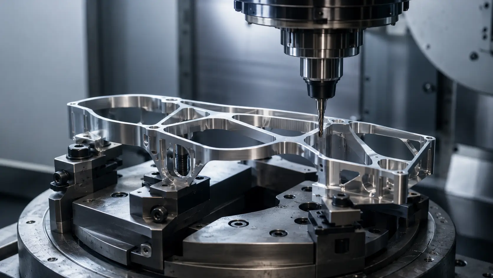
A thin-walled part clamped too aggressively can deform elastically under the fixture load. It measures correctly while still held, then springs back to a different shape once released. If the validation depends on flatness, alignment, sealing, or an assembly fit measured in the free state, that clamping-induced difference doesn’t show up until the part is off the machine.
Workholding strategy at prototype stage isn’t only a cost decision. For a flexible part, it can determine whether the geometry being measured is the part’s real geometry or a temporarily coerced one. For this reason, ZH Prototyping reviews workholding together with the free-state geometry that the prototype is intended to validate, particularly when thin or flexible features may respond to clamping force.
CNC Prototype Design Mistakes That Increase Lead Time
Prototype delays usually start before the machine ever runs, and they come from two distinct sources that call for different fixes.
Geometry Problems
Tool-inaccessible geometry, feature relationships that don’t reflect how the part will actually be held, tolerances tighter than the validation objective requires, and critical surfaces left undefined all create risk.
A shop has to resolve that risk before it can commit to a machining plan with any confidence. Resolving it means a strategy change, an added setup, a different tool, or a fixture redesign, and that work has to happen before programming can proceed, not after.
Drawing and Documentation Problems
Conflicts between the 3D model and the drawing, a datum scheme that isn’t clearly defined, missing thread callouts, undefined finish requirements, and critical dimensions with no stated reference create a different kind of problem: outright ambiguity rather than difficulty.
A shop can often machine a dimension exactly as written and still have no way to confirm whether the resulting feature sits correctly relative to the rest of the part, because nothing on the print told it what “correctly” means. A datum change that arrives after CAM programming has already started isn’t a documentation inconvenience. It can invalidate the setup references, the fixture orientation, the machining sequence, and the toolpaths already built against the datum scheme that just changed.
From CNC Prototype to Production: What Changes
A prototype that validates the design isn’t the same thing as a manufacturing definition ready for volume. The gap between the two is usually larger than it looks once the part is sitting on the bench working correctly.
Decisions that made sense at prototype stage, like a general-purpose fixture, a substitute material, a simplified non-functional feature, or a tolerance left loose because nothing depended on it, get revisited once quantity and design certainty both increase.
Final geometry gets reconciled against what was simplified for convenience rather than for the test. Material gets specified for real, not for whatever machined fastest. Tolerances and GD&T get formalized against production requirements instead of the narrower set that mattered for validation. Fixturing shifts toward dedicated tooling where the volume justifies it, and inspection strategy moves from checking a single part thoroughly toward a sampling approach appropriate to a stable, repeatable process.
None of this is automatic, and none of it applies uniformly. Only the choices made specifically because they didn’t affect the prototype’s validation objective need to be reconsidered. Anything already built to represent production doesn’t need to change just because the part is heading into a production quote.
CNC Prototype DFM Review at ZH Prototyping
A useful DFM review at prototype stage isn’t only checking whether a part can be cut. It’s checking whether the design, as drawn, will actually produce a part that answers the question it was built to answer.
That means looking at the same factors this article has worked through: CAD geometry and the 2D drawing together, material, quantity, the stated validation objective, tool access, setup and workholding requirements, thin or flexible features at risk of clamping distortion, which tolerances are actually critical, datum strategy, surface finishing, and inspection requirements.
The goal of that review is catching ambiguity and risk before they turn into a requote, a reprogrammed toolpath, a rebuilt fixture, or a part that has to be scrapped and rerun.
FAQ
It depends on what the prototype is validating. If the test is checking geometry, fit, or assembly, a substitute material that machines faster or costs less is usually fine. If the test depends on stiffness, strength, thermal behavior, wear, or corrosion, the substitution changes the result along with the material, and production material becomes necessary.
Another iteration is warranted when the last one left engineering uncertainty that actually affects the decision in front of the team, not on a predetermined number of rounds. If the previous build answered its question cleanly, another iteration adds cost without adding information. If it didn’t, the uncertainty it left behind is the reason to build again.
Tolerance should follow the same logic as everything else in the design: tight control where dimensional variation could be mistaken for or could mask a design result, general tolerance everywhere else. Tightening the whole print by default adds machining and inspection time without making any single test more trustworthy.