
This guide covers how HPDC actually works: the hot chamber and cold chamber processes, the four stages of a casting cycle, the aluminum, zinc, and magnesium alloys used in production, the design rules that keep a die castable, and the tolerances and defects an engineer should plan around before a part goes to tooling.
What Is High Pressure Die Casting (HPDC)
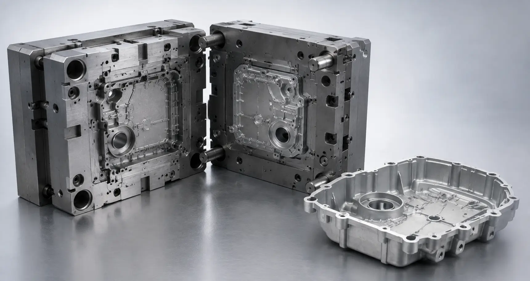
High pressure die casting is a metal casting process in which molten metal is injected into a permanent steel mold, or die, under high pressure and held there until the part solidifies. Unlike sand casting or investment casting, which use expendable molds, the die in HPDC is reusable and typically machined from hardened tool steel, since it has to withstand a high number of cycles at high pressure and temperature over its service life.
The process is built for volume. A single die can produce tens of thousands to hundreds of thousands of parts before it needs rework, and cycle times for smaller parts often run under a minute. That combination of speed and repeatability is why HPDC dominates production of automotive structural components, engine and powertrain parts, and housings for consumer electronics, where the tooling cost is justified by high part counts.
HPDC is generally limited to non-ferrous alloys with lower melting points, primarily aluminum, zinc, and magnesium. Casting steel or other high-melting-point metals isn’t a pressure limitation so much as a thermal one: their melting points sit close to or above what hardened tool steel dies can withstand in repeated service, causing rapid thermal fatigue, erosion, and soldering that would make the die uneconomical within a small fraction of its normal service life.
Hot Chamber vs. Cold Chamber Die Casting
HPDC splits into two distinct machine types, and the choice between them is driven almost entirely by the alloy being cast.
Hot Chamber Die Casting Process
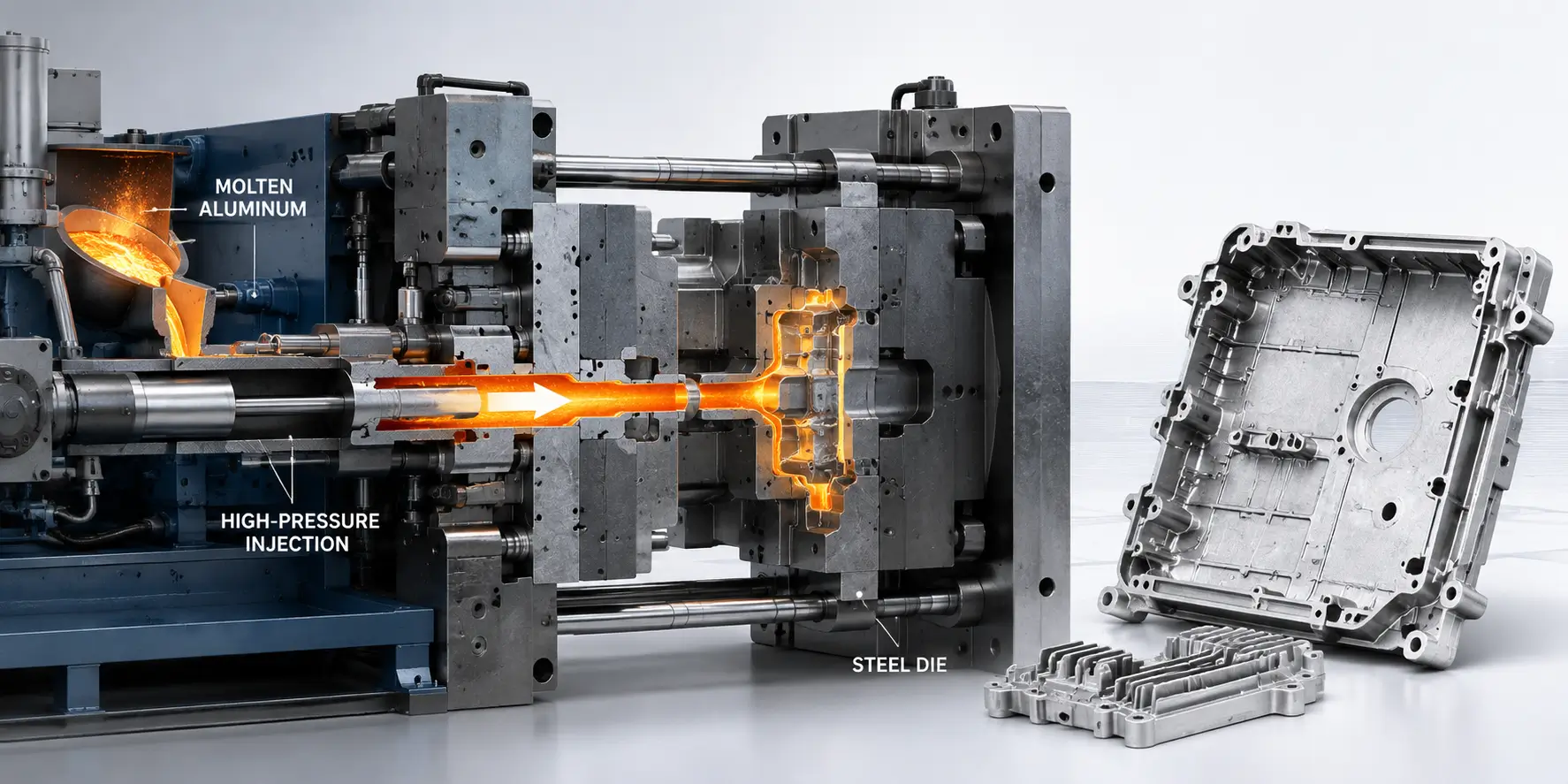
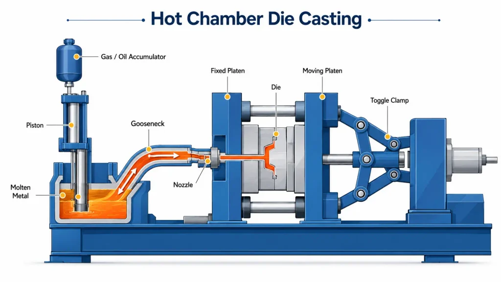
In hot chamber die casting, the injection mechanism sits submerged in a reservoir of molten metal. A gooseneck channel draws metal directly from the melt, and a hydraulic piston forces it through the gooseneck into the die cavity. Because the metal never leaves the machine between melting and injection, cycle times are fast and the process runs efficiently at high volume.
The limitation is thermal. The injection components stay in constant contact with molten metal, so hot chamber machines are restricted to alloys with lower melting points that won’t degrade the pump and gooseneck over time. Zinc and magnesium alloys are the primary candidates; aluminum is not run in hot chamber machines because it attacks the steel components at that temperature.
Cold Chamber Die Casting Process
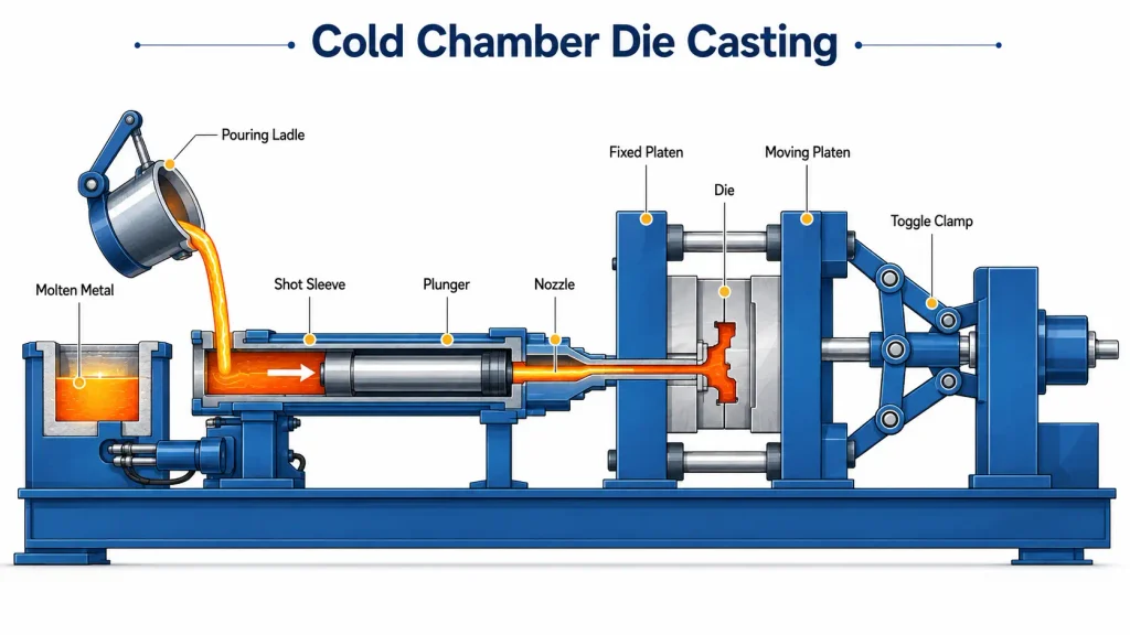
In cold chamber die casting, molten metal is ladled or automatically dosed into a separate shot sleeve for each cycle rather than staying in contact with the injection system. A plunger then drives the metal from the shot sleeve into the die. This adds a step to the cycle compared to hot chamber, but it isolates the injection hardware from constant exposure to the melt.
That isolation is what makes cold chamber suitable for aluminum, along with higher-temperature zinc and magnesium alloys where hot chamber isn’t an option. Nearly all aluminum HPDC, including the automotive structural castings and EV housings that make up a large share of current production, runs on cold chamber machines.
High Pressure Die Casting Process Steps
Regardless of hot or cold chamber, the die casting process follows four core stages. Each stage introduces its own set of process variables, and problems traced back to a defect in the finished part usually trace back to one of these four.
Die Preparation and Clamping
Before each shot, the die is cleaned and a lubricant is sprayed across the cavity surface. The lubricant serves two purposes: it helps regulate die temperature shot to shot, and it forms a film that allows the solidified part to release from the steel without galling or sticking. The two die halves are then closed and clamped with enough force to resist the injection pressure that follows; clamping force on production HPDC machines commonly ranges from a few hundred to several thousand tons, sized to the projected area of the part and the injection pressure being used.
Injection and Fill
Molten metal is driven into the die cavity, typically completing the fill in under 100 milliseconds. Fill velocity is usually staged: an initial slower phase moves metal toward the gate without excessive turbulence, followed by a rapid second phase once the metal is committed to the cavity, filling thin sections before the leading edge of the metal front can cool and solidify prematurely. Runners and gates are engineered to direct this flow, and vents or overflow wells are positioned to let displaced air escape ahead of the metal rather than get trapped inside the casting.
Intensification and Solidification
Once the cavity is full, pressure is increased and held during solidification. This intensification phase forces additional metal into the cavity to compensate for shrinkage as the casting cools, which is one of the mechanisms HPDC uses to achieve better density than gravity-fed casting methods. Cooling channels built into the die extract heat rapidly during this stage, and the cooling rate has a direct effect on grain structure and, downstream, on the mechanical properties of the finished part.
Ejection and Trimming
Once the casting has solidified enough to hold its shape, the die opens and ejector pins push the part free. Draft angles on the die walls exist specifically to let this happen without the part dragging against the steel; insufficient draft is a common cause of ejection damage or die wear. The part that comes out isn’t finished yet: it’s still attached to the biscuit, runners, and any overflow wells, which are removed in a trim press before the part moves on to secondary operations such as deburring, shot blasting, or machining of features that need tighter control than casting alone can hold.
Materials for High Pressure Die Casting
Alloy selection in HPDC is narrower than in CNC machining, since the process itself limits the field to metals that flow well at achievable temperatures and don’t attack the die.
Aluminum Alloys for Die Casting
Aluminum is the most widely used HPDC material for structural and load-bearing applications, chosen for its strength-to-weight ratio, corrosion resistance, and ability to hold complex thin-walled geometry. Common die casting grades include 380, 383, 390, and A413, each balancing castability, strength, and machinability differently. Aluminum HPDC runs on cold chamber machines and is the dominant material for automotive structural parts, engine components, and EV battery and motor housings.
Zinc Alloys for Die Casting
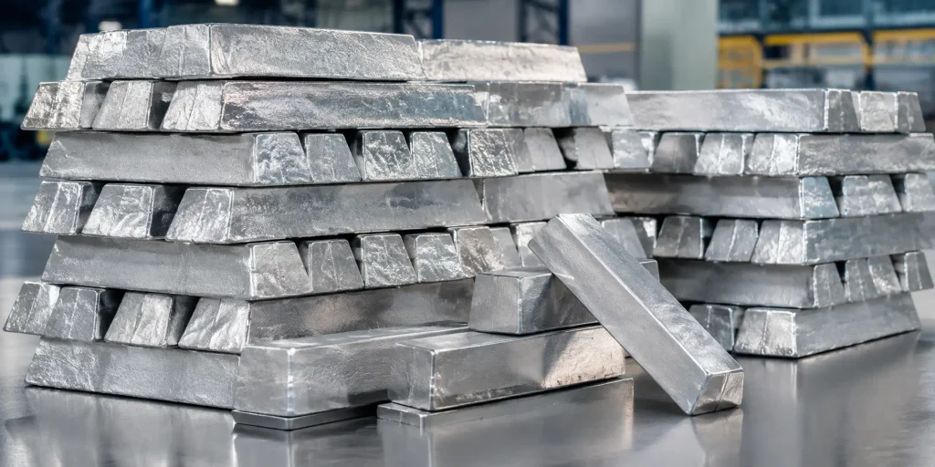
Zinc alloys offer noticeably better ductility and impact resistance than die cast aluminum, along with a lower melting point that makes them well suited to hot chamber casting and lets them fill thin sections and fine detail more easily than aluminum can. That combination is why zinc shows up in small precision components, connectors, and decorative hardware where dimensional detail and toughness matter more than weight savings; tensile strength between the two is comparable and depends more on the specific alloy grade than on zinc versus aluminum as a category.
Magnesium Alloys for Die Casting
Magnesium is the lightest structural metal commonly die cast, used where weight reduction is the priority and the part doesn’t need aluminum’s higher strength. It can run in either hot or cold chamber machines depending on the specific alloy and part size. Magnesium requires more careful handling during melting and machining due to its reactivity, which affects both foundry practice and downstream secondary operations.
Design Guidelines for High Pressure Die Casting (DFM)
A die casting design has to account for how metal actually fills and cools inside a closed steel cavity, which is a different set of constraints than machining a part from solid stock.
Wall Thickness and Draft Angles
Wall thickness in HPDC has a narrower usable range than in machining. Walls that are too thin risk short shots, where the metal solidifies before completely filling the cavity; walls that are too thick slow cooling and increase the risk of porosity and sink marks. The target thickness depends on the alloy and part geometry, so a specific number should come from the die caster’s process capability rather than a generic rule of thumb. Draft angles on every vertical surface are required for ejection, and the appropriate angle depends on wall height, texture, and alloy; deeper or textured cavities generally need more draft than shallow, smooth ones.
Ribs, Bosses, and Undercuts
Ribs are commonly used to add stiffness without adding wall thickness, since a thick, solid section cools more slowly and is more prone to shrinkage porosity than a thinner wall reinforced with ribs. Rib thickness is usually kept below the adjoining wall thickness to avoid a sink mark forming on the visible face opposite the rib as the thicker intersection cools unevenly. Bosses for fasteners or locating features follow a similar logic, and undercuts should be minimized or handled with die-side actions, since every undercut adds a moving core or slide to the tooling, which increases both die cost and cycle complexity. During DFM review at ZH Prototyping, an undercut that could be redesigned as a straight-pull feature is usually flagged early, since it changes the tooling quote as much as it changes the part.
Parting Line and Gate Location
The parting line, where the two die halves meet, and the gate, where metal enters the cavity, are usually decided early in tooling design because they affect nearly everything downstream: how the part ejects, where flash is likely to form, and how evenly the cavity fills. Gates are typically placed to direct metal into the thickest sections first and let it flow toward thinner areas, which helps avoid premature freezing in thin walls before the cavity is fully packed. Parting line placement also determines where visible flash lines will fall on the finished part, which matters for parts with cosmetic surfaces.
Achievable Tolerances in High Pressure Die Casting
HPDC produces tighter as-cast tolerances than sand casting or gravity die casting, but it still can’t match the dimensional control of CNC machining on every feature. As-cast tolerances are generally tightest on dimensions controlled entirely within one die half, since those aren’t affected by parting line shift or die wear over the tool’s life. Dimensions that span the parting line, or that depend on core or slide position, typically carry looser tolerances because they’re subject to additional sources of variation in the tooling itself.
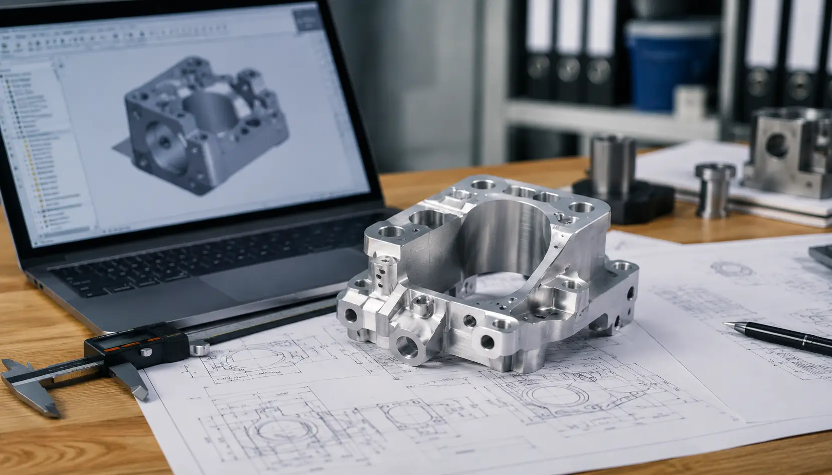
For features that need tighter control than die casting alone can reliably hold, such as bearing bores, sealing surfaces, or precision mounting interfaces, the common approach is to cast the part net or near-net and machine the critical features afterward. Specifying which dimensions are cast-tolerance and which require secondary machining, rather than applying one tolerance class across the whole part, keeps both the die cost and the part cost proportional to what the design actually needs. Tolerance review at ZH Prototyping typically starts from the drawing’s parting line and gate assumptions before confirming which features are realistic to hold as-cast.
Common High Pressure Die Casting Defects and Causes
Most die casting defects in HPDC trace back to how the metal fills and cools, which is why defect analysis usually starts by looking at the process stage rather than the part in isolation.
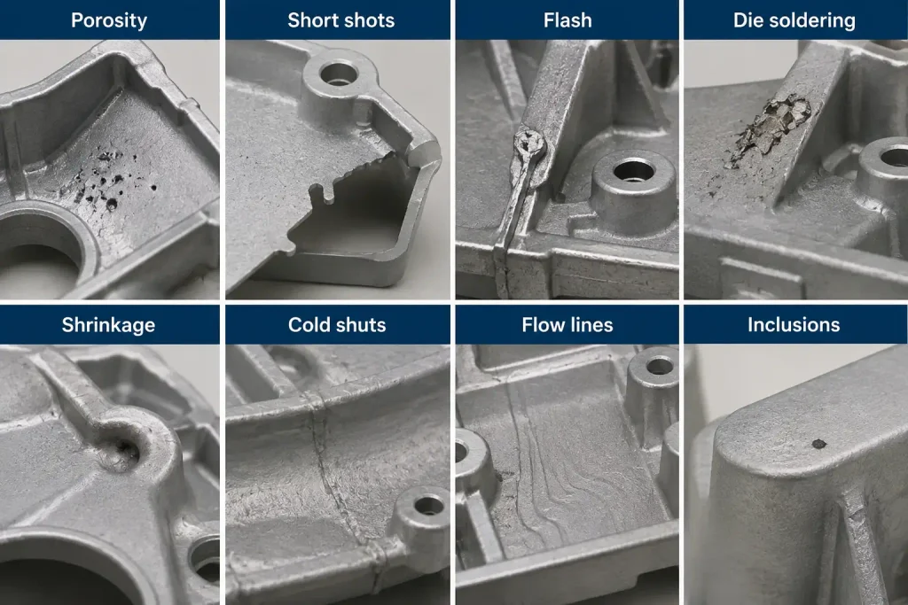
Porosity is the most common defect category and comes in two forms. Gas porosity forms when air trapped during the high-speed fill gets entrained in the metal instead of escaping through vents; shrinkage porosity forms when a thick section cools and contracts without enough metal being fed in during intensification to compensate. The two require different fixes, since one is a venting and fill-speed problem and the other is a wall-thickness and gating problem.
Short shots occur when the metal front cools and begins to solidify before the cavity is completely filled, leaving the casting incomplete, often in thin sections far from the gate or in parts run with insufficient injection speed or metal temperature. Cold shuts are a related but distinct defect: two separate flow fronts meet inside the cavity after each has already begun to solidify, and the fronts fail to fuse where they meet. The cavity may still fill completely, but the unfused line leaves a visible seam and a local weak point in the casting.
Flash is excess metal that escapes at the parting line or around moving die components, usually a sign of insufficient clamping force relative to injection pressure, or wear at the parting line over the die’s service life.
Die soldering happens when molten metal reacts with and adheres to the die steel, most often with aluminum alloys with insufficient iron content or with local hot spots in the die where cooling isn’t keeping pace with the alloy’s tendency to solder.
Advantages and Limitations of High Pressure Die Casting
HPDC’s core advantage is producing complex, near-net-shape geometry at high volume with a level of dimensional repeatability that other casting processes don’t match. The trade-off is upfront cost and flexibility: tooling is expensive and slow to produce, since a hardened steel die has to be machined to hold tight geometry through many high-pressure, high-temperature cycles over its service life, and that cost only makes sense once production volume justifies it.
| Advantages | Limitations |
|---|---|
| High dimensional repeatability shot to shot, once the die is qualified | High tooling cost and long lead time before the first production part |
| Complex, near-net-shape geometry achievable in a single shot | Not economical below production-level quantities; CNC machining or 3D printing is almost always more practical for prototypes or low-quantity runs |
| Thin walls and fine surface detail beyond what sand or investment casting can hold | As-cast porosity from trapped gas during high-speed fill |
| Part consolidation, where several previously separate components are combined into one casting | Trapped gas can expand and blister the part under the heat of welding or some heat treatment processes |
| Fast cycle times sustain high output once the die is in production | Vacuum-assisted HPDC is often needed to control porosity for applications where welding or heat treatment is required |
High Pressure Die Casting Applications
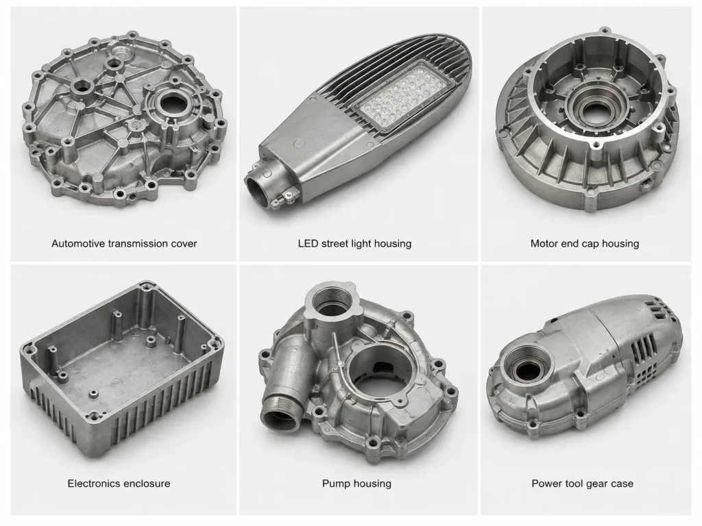
Automotive is the largest application for HPDC, spanning engine blocks, transmission and gearbox housings, structural chassis components, and, increasingly, large-format aluminum castings for EV battery enclosures and structural underbodies, where consolidating dozens of stamped and welded parts into a single die casting reduces both weight and assembly steps.
Beyond automotive, HPDC is used across consumer electronics for enclosures and structural brackets, industrial equipment for housings and gearboxes, and, in select cases, medical devices where lightweight metal components are needed at volume. Aerospace uses HPDC more selectively, generally for non-flight-critical components, since the porosity inherent to standard HPDC makes it a harder fit for parts subject to the fatigue and certification requirements common in flight-critical structures.
High Pressure Die Casting at ZH Prototyping
When a die casting drawing comes in without a clear split between as-cast tolerance zones and features that need secondary machining, that’s usually the first thing clarified during DFM review at ZH Prototyping, since it changes both the tooling design and the part’s finishing sequence. The same applies to material grade: an aluminum callout without a specific alloy designation gets confirmed before quoting, since 380 and 390 behave differently enough in the die that the choice affects wall thickness and gating decisions.
FAQ
Hot chamber machines keep the injection system submerged in molten metal, which makes them fast but limits them to lower-melting-point alloys like zinc and magnesium. Cold chamber machines ladle metal into a separate shot sleeve for each cycle, adding a step but allowing higher-temperature alloys like aluminum to be cast without damaging the injection hardware.
As-cast tolerances are generally tighter on features controlled within a single die half and looser on features that span the parting line or depend on core position. For dimensions that need tighter control than casting can reliably deliver, the typical approach is casting the part net or near-net and machining the critical features afterward, rather than applying one tolerance class across the entire part.
Porosity comes from two different sources: trapped gas that doesn’t escape during the high-speed fill, and shrinkage in thick sections that don’t receive enough additional metal during intensification as they cool. Because the causes are different, gas porosity is typically addressed through venting and fill-speed adjustments, while shrinkage porosity is addressed through wall thickness and gating design.