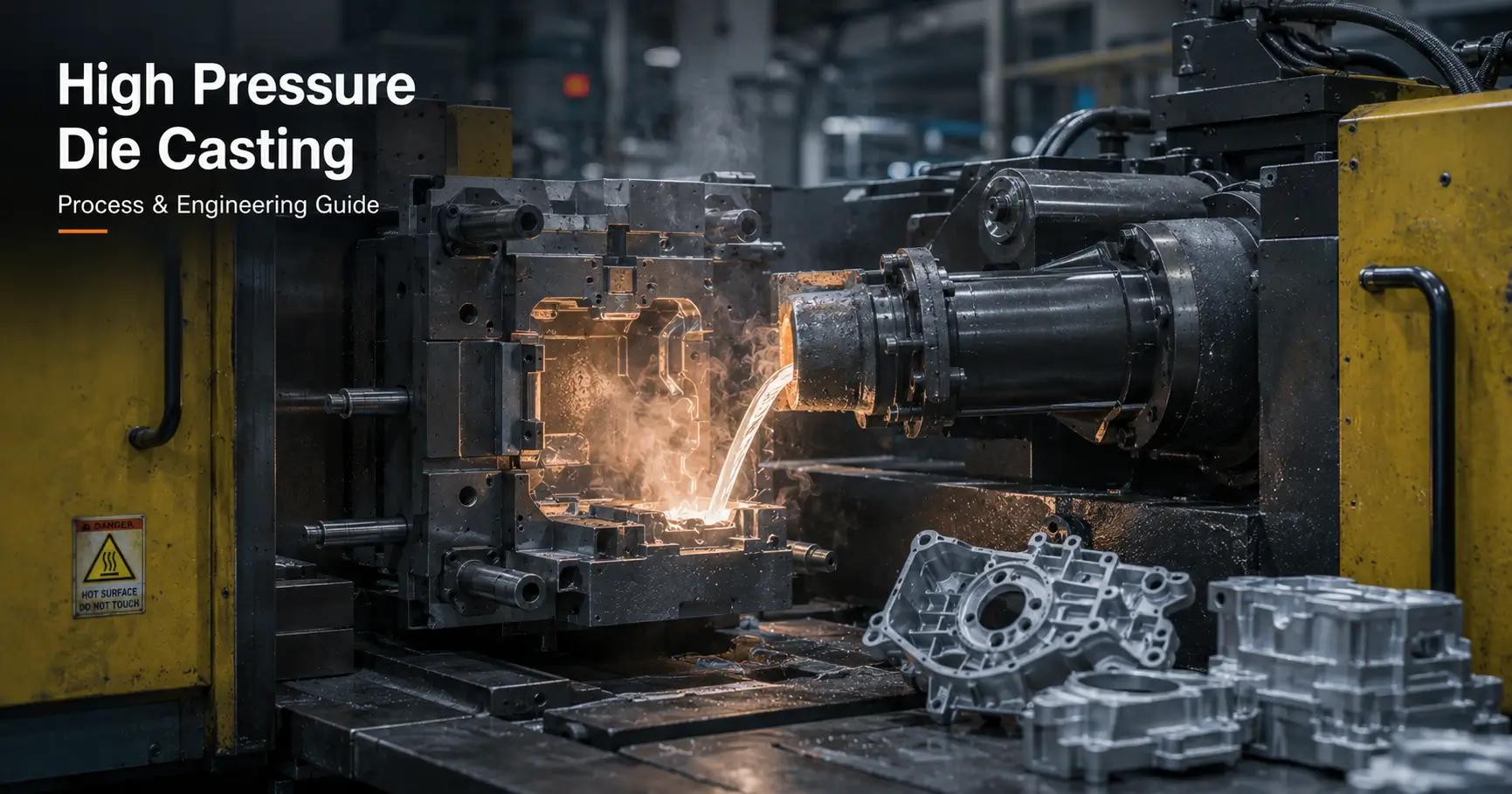

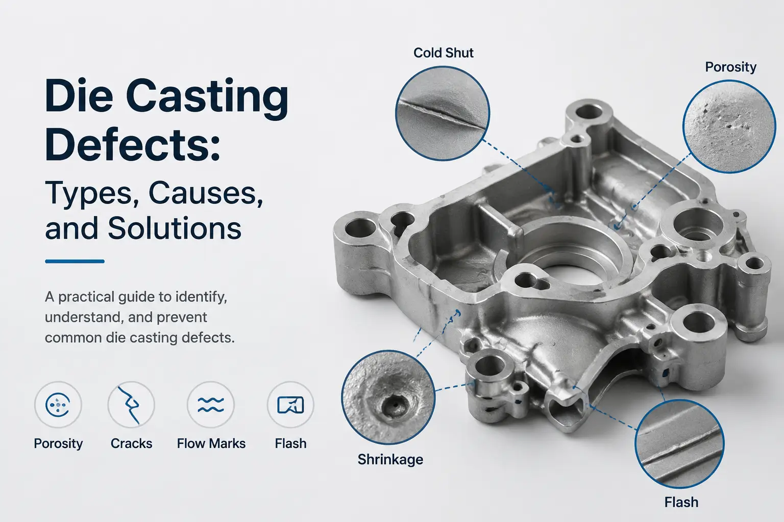
This guide covers the most common die casting defects, organized by where they originate: part design, die and gating design, process conditions, and material quality. Each section includes the root causes and practical solutions, followed by a quick-reference matrix, commonly confused defect pairs, and a broader framework for solving defects systematically.
Defects Caused by Part and Die Design
1. Shrinkage Porosity
Shrinkage porosity appears as irregular voids or cavities, usually forming in the thickest sections of a casting or at the last areas to solidify. Under X-ray or CT inspection, it typically has a jagged, dendritic outline rather than the smooth round shape seen with trapped gas, which is one of the first things an engineer checks when trying to separate it from gas porosity during a defect investigation.
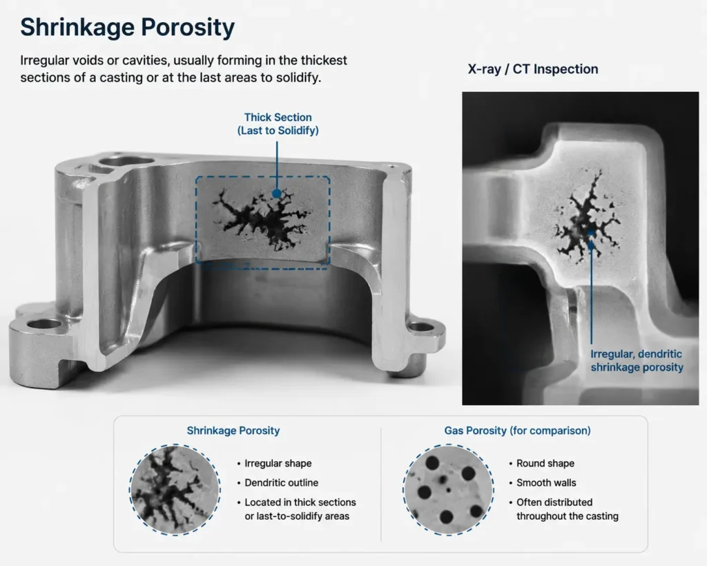
Causes: Molten metal contracts as it cools. If there isn’t enough liquid metal available to feed a section as it solidifies, a void forms. This is most common at abrupt wall-thickness transitions, isolated thick bosses, or ribs that create isolated “hot spots” far from the gate, essentially any region with a higher thermal modulus than the metal feeding it.
Aluminum alloys are particularly prone to this because they carry a comparatively wide freezing range and shrink several percent by volume as they solidify. Any section that is thermally isolated from the gate is at risk, even when the overall wall thickness looks reasonable on a drawing.
Solutions:
- Design parts with uniform wall thickness and generous fillets at transitions to avoid isolated hot spots.
- Position gates to feed thick sections last, maintaining pressure on them as they solidify.
- Apply intensification (secondary) pressure to push additional metal into shrinking regions before they freeze.
- Use flow and solidification simulation to identify hot spots before the die is cut.
As part of ZH Prototyping’s custom die casting services, engineers perform thermal modulus analysis during DFM review to identify isolated thick sections and recommend design, rib, or gating improvements before tooling begins. This helps reduce shrinkage risks and avoids costly corrections after initial die trials.
2. Hot Tears and Cracks
Hot tears show up as jagged, irregular cracks, often at corners, thickness transitions, or areas of restricted contraction, sometimes with a discolored, oxidized surface inside the crack.
Causes: As the casting cools, it wants to shrink freely. If the die geometry, ejector pins, or an internal core restrain that shrinkage, internal stress builds up while the metal is still weak and partially solidified, and it tears rather than deforms.
This weak window sits within what metallurgists call the brittle temperature range, the span between the alloy’s solidus and the point where it has enough solid fraction to carry load. Alloys with a wide freezing range, common in many die casting aluminum alloys, spend more time in that vulnerable state than narrow-range alloys do.
Solutions:
- Avoid sharp internal corners and abrupt section changes that concentrate stress.
- Add relief or taper to cores and die features that could lock the casting in place during cooling.
- Balance cooling so that no single area solidifies drastically later than the rest.
- Select an alloy with better hot-tearing resistance if the geometry can’t be changed.
3. Warpage
Warpage is a bend, twist, or bow in the finished part relative to its intended geometry, usually discovered during dimensional inspection or assembly fit-up. On production parts, it’s typically caught with CMM measurement against the CAD model or with dedicated go/no-go fixtures on high-volume lines, since visual inspection alone often misses distortion below a few tenths of a millimeter that can still cause a mating part to bind.
Causes: Uneven cooling rates across the casting, driven by inconsistent wall thickness, asymmetric die temperature, or premature ejection, cause different regions to contract at different rates and different times.
Solutions:
- Keep wall thickness as uniform as possible across the part.
- Balance the die’s cooling channel layout so both halves and all regions cool evenly.
- Avoid ejecting the part before it has sufficient rigidity to hold its shape.
- Use simulation to predict distortion and pre-compensate the die geometry if needed.
Defects Caused by Die and Gating System Design
1. Cold Shuts
Cold shuts appear as a visible line or seam where two flow fronts met but didn’t fully fuse, often on thin walls or far from the gate.
Causes: When molten metal splits around a core or obstruction and the separate streams have cooled too much by the time they rejoin, they solidify without properly bonding, leaving a weak, sometimes visible seam.
Aluminum alloys make this worse than it looks on paper. The melt forms a thin oxide skin almost instantly on contact with air or a cool die wall, and if two flow fronts meet after that skin has formed, they can look fully merged on the surface while remaining mechanically unbonded underneath. This is why cold shuts sometimes only show up under load or during machining.
Solutions:
- Increase gate size or injection speed so metal reaches distant areas while still hot enough to fuse.
- Relocate gates to shorten flow paths and reduce the number of flow fronts that must reunite.
- Raise metal or die temperature slightly to extend fill time.
- Avoid unnecessarily thin sections that cool the flow front too quickly.
2. Flow Marks
Flow marks are visible streaks or wavy lines on the casting surface that trace the path molten metal took while filling the cavity.
Causes: Turbulent or inconsistent flow, often from poor gate placement, undersized runners, or an uneven flow front, leaves a visual record on the surface as the metal cools at different rates along its path.
Flow marks are usually a cosmetic issue rather than a structural one. But on parts headed for anodizing, plating, or a Class A painted finish, they need the same level of process attention as a structural defect, since post-processing tends to make surface flow patterns more visible, not less.
Solutions:
- Optimize gate location and runner sizing for a smooth, progressive fill.
- Use flow simulation to identify and eliminate turbulence before cutting the die.
- Adjust injection speed profile so the flow front advances steadily rather than in bursts.
3. Cuts and Washes (Die Erosion)
Cuts and washes appear as raised or eroded areas on the casting surface, mirroring localized wear on the die cavity.
Causes: High-velocity molten metal impinging directly on a die surface, often due to a poorly angled gate or excessive injection speed, erodes the die over time, and that erosion transfers to every subsequent part.
Gate velocities in aluminum die casting commonly run well above 30 m/s at the gate itself. Even a modest misalignment between the gate and the opposing die wall concentrates that energy on one spot instead of spreading it across the cavity, and hardened tool steels like H13 will still erode under sustained impingement at that velocity.
Solutions:
- Angle gates so metal doesn’t blast directly onto a die wall or core.
- Use wear-resistant die steel and coatings in high-erosion zones.
- Moderate injection speed once the cavity begins to fill, rather than holding peak velocity throughout.
- Inspect and refurbish eroded die areas on a scheduled maintenance cycle.
Defects Caused by Process Conditions
1. Gas Porosity
Gas porosity presents as small, round or oval voids, typically with a smooth internal surface, distributed through the body of the casting rather than concentrated in one thick section.
Causes: Air trapped in the die cavity during rapid, turbulent filling, or gas dissolved in the molten metal itself, becomes trapped as bubbles when the metal solidifies around it.
In cold chamber die casting, a meaningful share of that trapped air actually originates in the shot sleeve itself. If the sleeve isn’t filled to an adequate percentage before the plunger advances, air above the metal gets rolled into the melt from the very start of the shot, before it ever reaches the gate.
The ASM Handbook, Volume 15: Casting, published by ASM International, identifies shrinkage porosity and gas porosity as the two fundamental porosity mechanisms in castings, each requiring a distinct diagnosis before it can be corrected. In practice, that diagnosis is usually made by cross-sectioning a sample and examining void shape under magnification, or by X-ray and CT scanning for internal, non-destructive inspection on production parts.
Solutions:
- Improve venting design so trapped air has a clear escape path as the cavity fills.
- Reduce injection speed during the initial fill phase to limit turbulence and air entrapment.
- Maintain an adequate shot sleeve fill percentage so the first-phase plunger movement doesn’t churn air into the melt before it reaches the gate.
- Consider vacuum-assisted die casting for pressure-tight or structurally critical parts.
- Keep melt handling practices (degassing, clean charge material) consistent to limit dissolved gas.
2. Flash
Flash is a thin, excess layer of metal that escapes along the parting line, around ejector pins, or at other die interfaces.
Causes: Flash occurs when the clamping force isn’t sufficient to counter the injection pressure, or when the parting surfaces don’t seat tightly due to die wear, contamination, or misalignment.
Required clamping tonnage is a function of the part’s projected area at the parting line multiplied by cavity pressure. Flash is often the first symptom that shows up when a die is rebuilt with added cavities, or when a part is quoted on a machine that’s undersized for its projected area, even if every other process parameter is correct.
Solutions:
- Confirm machine tonnage is adequate for the part’s projected area and injection pressure.
- Keep parting surfaces clean and well-maintained, and correct any die misalignment promptly.
- Optimize injection pressure so it fills the cavity without exceeding what’s needed.
3.Misruns (Short Fills)
A misrun is an incompletely filled casting, most often visible as a missing or thin section, typically at the point in the cavity farthest from the gate.
Causes: The molten metal solidifies before it reaches the far end of the cavity, usually from insufficient injection speed or pressure, a metal temperature that’s too low, or trapped gas blocking the flow path.
Thin-walled sections are especially vulnerable because they present a high surface-area-to-volume ratio to the die steel. The flow-length-to-wall-thickness ratio for a given alloy and die temperature effectively sets a ceiling on how far metal can travel through a thin rib before it freezes short.
Solutions:
- Increase injection speed and pressure so the cavity fills before the leading edge cools too far.
- Verify metal temperature is within the process window for the alloy and part geometry.
- Improve venting so trapped air isn’t blocking the last areas to fill.
- Reassess gate location for parts with long, thin flow paths.
4. Blistering
Blistering shows up as a raised bubble or bump on the casting surface, sometimes appearing only after heat treatment or painting, when trapped gas near the surface expands.
Causes: Gas or air trapped just beneath the surface, from turbulent fill or excess lubricant/release agent, expands when the part is later exposed to heat, pushing the surface outward.
This is the practical reason high-pressure die castings are rarely solution heat treated the way sand or permanent mold castings sometimes are. Trapped gas that’s invisible at room temperature expands violently at the solution-treatment temperatures those processes require, and blistering is the most common result.
Where higher mechanical properties are needed on an HPDC part, the more common path is switching to a vacuum-assisted or pore-free process, or selecting a heat-treatable alloy specifically qualified for it, rather than heat treating a standard conventionally-cast part after the fact.
Solutions:
- Reduce turbulence and air entrapment during fill, as with gas porosity.
- Apply die lubricant sparingly and evenly rather than in excess.
- Allow adequate cooling time before ejection to reduce near-surface gas pockets.
Defects Caused by Material and Metal Quality
1.Inclusions
Inclusions are foreign particles, such as oxides, slag, or contamination, embedded within the casting, often creating a localized weak point or surface blemish.
Causes: Contaminated furnace charge material, inadequate slag/dross removal before pouring, or excessive graphite-based release agent can all introduce foreign material into the melt.
Inclusions rarely show up as a visible surface defect until machining exposes them. Incoming alloy is normally checked with optical emission spectrometry (OES) against the target composition rather than relying on visual inspection of the ingot or return material alone.
Solutions:
- Use clean, well-sourced metal charge material and verify alloy certification.
- Skim dross regularly during the holding stage so it doesn’t mix back into the melt.
- Control the type and quantity of mold release agent used.
- Filter molten metal before injection where the process allows it.
2. Soldering
Soldering occurs when casting metal chemically bonds to the die surface, tearing away when the part is ejected and leaving rough patches on both the part and the die.
Causes: Elevated die temperature combined with insufficient or breakdown of the release agent lets the casting alloy react with and adhere to the die steel, most common in aluminum die casting.
Iron content in the alloy plays a real role here too. Iron is deliberately kept above a minimum level in most aluminum die casting alloys specifically because it suppresses this die-soldering reaction, which is part of why die casting alloys and general-purpose casting alloys aren’t always interchangeable even when their other properties look similar on a datasheet.
Solutions:
- Maintain die temperature within the recommended range for the alloy being cast.
- Apply release agent consistently and inspect its coverage in high-risk zones.
- Use a die steel and surface treatment suited to the alloy to reduce chemical affinity.
Master Die Casting Defects and Solutions Matrix
| Defect | Category | Primary Cause | Key Fix |
| Shrinkage Porosity | Design | Insufficient feed metal at hot spots | Uniform wall thickness, intensification pressure |
| Hot Tears / Cracks | Design | Restrained shrinkage during cooling | Generous fillets, relief on cores |
| Warpage | Design | Uneven cooling rates | Balanced cooling channels, uniform walls |
| Cold Shuts | Die / Gating | Flow fronts too cool to fuse | Larger gate, higher speed, higher metal temp |
| Flow Marks | Die / Gating | Turbulent or uneven flow | Optimized gate placement, flow simulation |
| Cuts and Washes | Die / Gating | High-velocity metal erosion | Gate angle correction, wear-resistant die steel |
| Gas Porosity | Process | Trapped air / dissolved gas | Improved venting, vacuum die casting |
| Flash | Process | Insufficient clamping force | Adequate tonnage, parting surface maintenance |
| Misruns | Process | Premature solidification | Increased speed/pressure, better venting |
| Blistering | Process | Near-surface trapped gas | Reduced turbulence, controlled lubricant |
| Inclusions | Material | Contaminated melt | Clean charge material, dross skimming |
| Soldering | Material | Die-to-metal chemical bonding | Temperature control, proper release agent |
Frequently Confused Die Casting Defects
Two defects that look nearly identical on the surface can have opposite root causes and opposite fixes, so misdiagnosing one for the other usually makes the problem worse rather than better.
This is why defect investigation on the shop floor typically starts with sectioning or X-ray before any process parameter gets changed, rather than adjusting the machine based on a visual guess.
Cold Shuts vs. Misruns: Both involve incomplete fusion or filling, but a cold shut is a visible seam where two flow fronts met and failed to bond, while a misrun is an entirely unfilled region where metal never arrived at all.
Gas Porosity vs. Shrinkage Porosity: Gas porosity voids tend to be small, round, and smooth-walled, scattered through the casting. Shrinkage porosity voids are irregular, concentrated in thick sections, and often have a rougher internal surface.
Flash vs. Flow Marks: Flash is excess material physically escaping the die at the parting line. Flow marks are a surface texture defect within the intended cavity, with no extra material involved.
How Manufacturers Prevent Die Casting Defects
Fixing one defect at a time works for a single bad shot. Reducing scrap rate across a whole production run takes a systemic approach, built into how the part, the die, and the process are managed from the start.
In practice, most recurring defects turn out to involve more than one contributing factor at once, a marginal gate design that only becomes a problem once die temperature drifts a few degrees, for example. This is why a durable fix usually has to address design, tooling, and process together rather than tuning a single machine parameter in isolation.
Design for Manufacturability (DFM)
Most die casting defects trace back to decisions made before the die is ever cut. Reviewing wall thickness uniformity, draft angles, rib-to-wall ratios, and gate/ejector locations during the design phase catches risks while they’re still cheap to fix.
At ZH Prototyping, this stage typically means engineers walking through part geometry, alloy selection, and proposed gate and vent placement together. A change that solves a shrinkage risk at the gate can just as easily introduce a new cold shut risk elsewhere if it’s reviewed in isolation.
Flow and Solidification Simulation
Mold-flow-style simulation for die casting predicts how metal will fill the cavity and where it will solidify last, surfacing likely porosity, cold shut, and air-trap locations before any steel is cut.
Scientific Process Control
Locking in a stable, documented process window, including injection velocity profile, intensification pressure, metal temperature, and die temperature, and holding it consistently from shot to shot prevents the drift that produces intermittent defects.
The North American Die Casting Association (NADCA), the leading U.S. industry association for die casting process training and standards, structures much of its defect-troubleshooting curriculum around this link between process parameters and specific defect types. That reinforces process discipline, not just die design, as central to defect control.
In-Process Monitoring
Shot-to-shot monitoring of key parameters (fill time, pressure curve, die temperature) flags variation before it produces a run of scrap, rather than discovering the problem at final inspection.
Preventive Die Maintenance
Parting surfaces, vents, ejector pins, and cooling channels all degrade with cycle count. A scheduled maintenance program catches wear-driven flash, erosion, and cooling imbalance before it shows up as a defect trend.
Non-Destructive and Dimensional Inspection
Process control reduces defect rates, but it doesn’t eliminate the need to verify the parts actually leaving the line. X-ray or CT scanning catches internal porosity and inclusions that no amount of visual inspection will find.
CMM or fixture-based dimensional checks confirm warpage and shrinkage haven’t pulled critical features out of tolerance, and pressure or leak testing verifies pressure-tight castings actually hold, referencing the applicable ASTM test methods and NADCA acceptance criteria for the part’s application.
At ZH Prototyping, this inspection data is tracked back to the process parameters for that production run, so a recurring defect can be traced to its root cause rather than treated as a one-off reject.
Conclusion
Die casting defects rarely come from a single cause. Most trace back to a combination of part geometry, die and gating design, process parameters, and material quality, which is why solving them takes more than adjusting one machine setting after a bad shot.
Identifying which category a defect belongs to, whether it’s shrinkage porosity from an unfed hot spot, a cold shut from a flow path that cooled too fast, or soldering from an overheated die, is the first step toward a fix that actually holds.
The most reliable path to consistently low scrap rates combines the practices covered above: design for manufacturability review before tooling, flow and solidification simulation to catch problems on screen instead of on the shop floor, a locked-in and monitored process window, and a preventive die maintenance schedule. Treated together as a system rather than isolated fixes, these practices turn defect troubleshooting from a reactive scramble into a predictable, manageable part of running a die casting operation.
Frequently Asked Questions
Porosity, both gas and shrinkage, is the most frequently encountered die casting defect, since it can originate from multiple sources: trapped air, dissolved gas, or insufficient feed metal during solidification.
Minor flash or cosmetic flow marks can often be corrected through secondary finishing. Internal defects like porosity, cracks, or inclusions typically can’t be reliably repaired and usually result in scrap for structural or pressure-tight parts. Resin impregnation can seal minor surface-connected porosity on non-critical parts, but it addresses the leak path, not the underlying strength loss.
Significantly. Uniform wall thickness, generous fillets, and gate locations that avoid isolated thick sections eliminate many of the conditions behind shrinkage porosity, hot tears, and warpage before the die is even built.
Internal defects, shrinkage porosity, gas porosity, cracks, and inclusions, pose the greatest risk to structural integrity, since they reduce the load-bearing cross-section and can act as stress concentration points.