
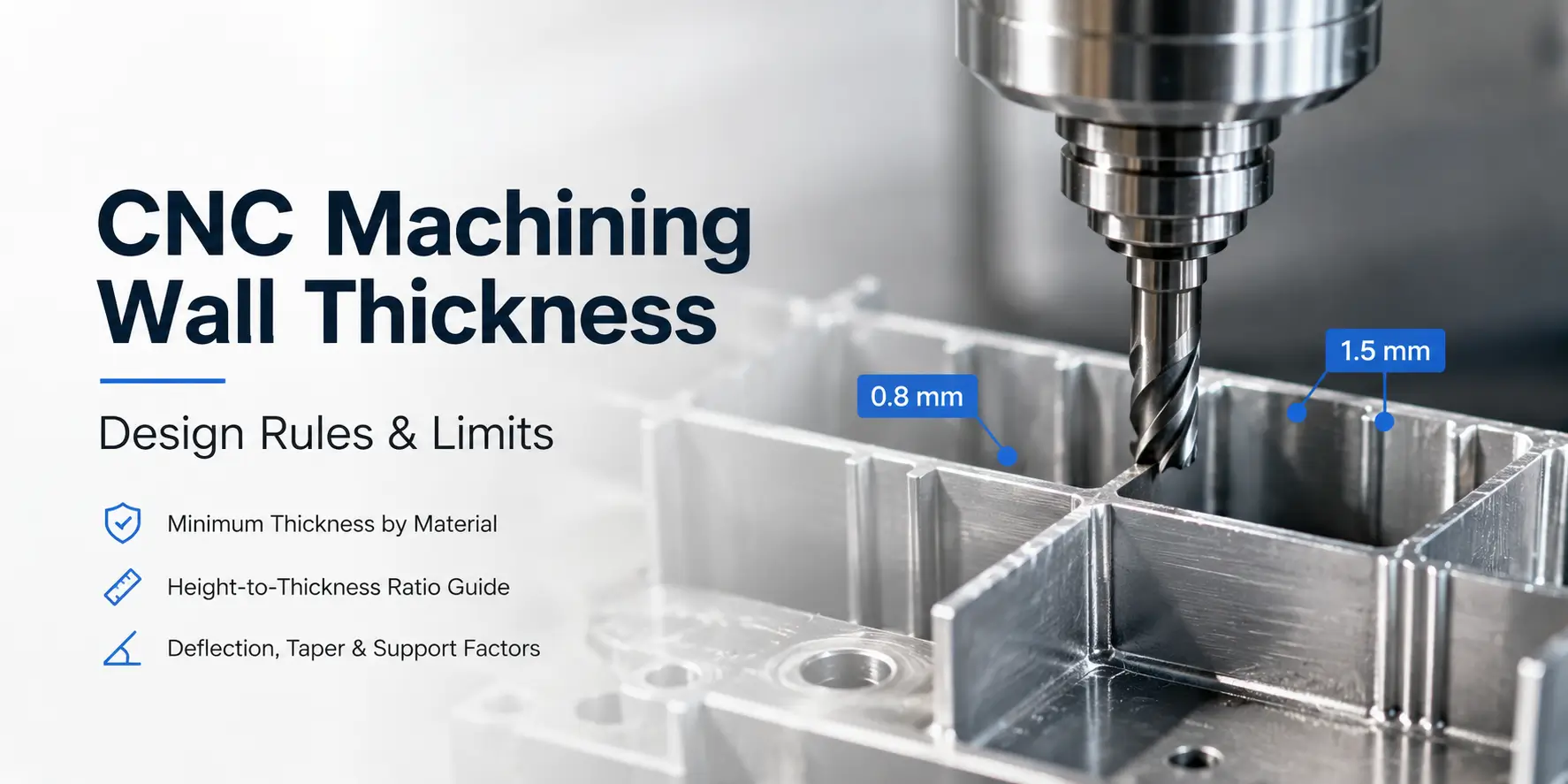
This guide covers what actually determines whether a wall machines reliably: minimum thickness by material, the height-to-thickness ratio used to screen risky features, why thin walls deflect and taper, and where ribs, tolerance, and workholding change the practical limit. The numbers here are design references, not fixed rules, since geometry and support conditions move the real limit as much as the material does.
What Is Wall Thickness in CNC Machining
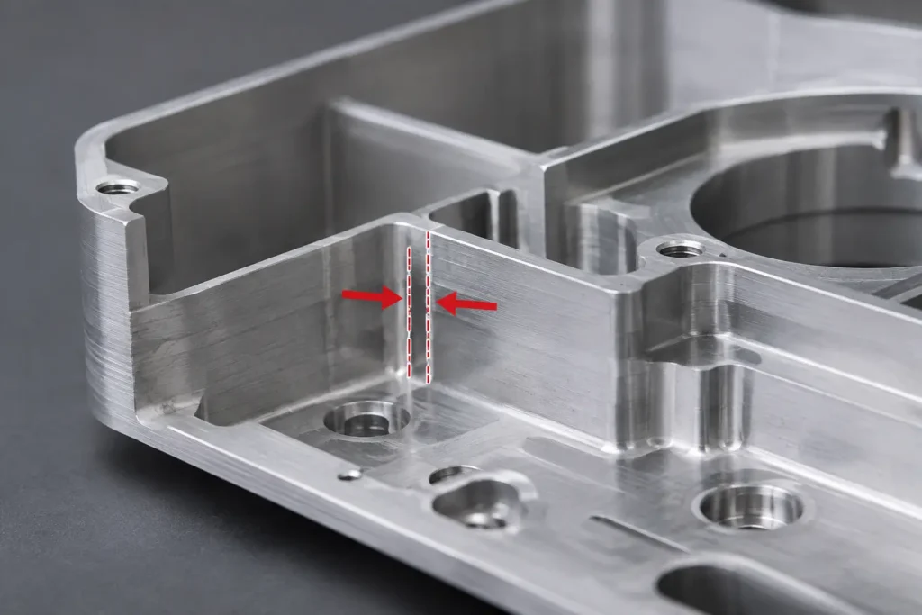
Wall thickness in CNC machining is the distance between two opposing machined surfaces after material removal, typically the thinnest cross-section left standing between a pocket, bore, or open face and the rest of the part.
It determines how much the wall resists cutting force during machining, not just how it performs in service. A wall that looks fine on the CAD model can still deflect, chatter, or taper if it can’t resist the load the tool applies while cutting.
Thinner walls change more than one thing at once. Stiffness drops, dimensional stability gets harder to hold, the machining strategy has to shift toward lighter cuts and more passes, and cycle time goes up. Wall thickness is one of the first things worth checking on a drawing before quoting, because it affects feasibility and cost together.
Minimum CNC Machining Wall Thickness by Material
There is no single minimum wall thickness that applies across materials and geometries. The number that matters depends on what “minimum” means: the thinnest wall that can technically be cut under favorable conditions, or the thinnest wall that machines reliably in normal production.
| Material | Feasible minimum | Recommended design value |
| Aluminum (6061, 7075) | 0.5 mm | 0.8 mm |
| Stainless steel (304, 316) | 0.8 mm | 1.0-1.2 mm |
| Carbon / alloy steel (1045, 4140) | 0.8 mm | 1.0-1.5 mm |
| Titanium (Ti-6Al-4V) | 1.0 mm | 1.5 mm |
| Brass (C360) | 0.4 mm | 0.6-0.8 mm |
| Copper (C110) | 0.5 mm | 0.8-1.0 mm |
These figures are general DFM references, not universal CNC standards. The feasible minimum assumes short, well-supported walls and controlled cutting parameters; the recommended value is what holds up across a wider range of wall heights and fixture conditions without extra process development. The practical limit for a specific part still depends on wall height, unsupported span, support conditions, pocket depth, tool reach, workholding, tolerance, and machining strategy.
A 0.5 mm aluminum wall that’s 3 mm tall and boxed in on three sides behaves nothing like the same 0.5 mm wall standing 20 mm tall with one edge free. Height, support, and pocket depth move the practical limit more than the material spec does.
Why Thin Walls Fail: The Physics of Deflection
A wall’s resistance to bending drops fast as thickness decreases, roughly with the cube of thickness. Cutting a wall from 1.0 mm to 0.5 mm doesn’t cut its stiffness in half, it cuts it to roughly an eighth. That’s why thin-wall problems tend to show up suddenly rather than gradually as designs get thinner.
During machining, the cutting edge pushes laterally on the wall. A stiff wall barely moves. A thin wall deflects away from the tool, which changes cutter engagement and removes less material than programmed, and the wall springs back once the tool passes. Uneven engagement across the wall height can also excite chatter instead of a clean cut, and the combined effect is a wall that measures too thick in the middle and closer to nominal at the ends, often described as taper or bow.
Clamping adds a second source of distortion. A thin wall pulled slightly out of shape by fixture pressure will machine to a clean dimension while clamped and read out of tolerance once released. This is a common cause of parts that pass an in-process check and fail final inspection.
Residual stress compounds both effects. Material removal can redistribute residual stress within the stock, causing a thin section or the overall part to move during machining or after it is released from the fixture. Thin sections have less mass to resist that movement, which is why they show it more readily than a thicker feature machined from the same stock.
A 0.8 mm aluminum enclosure wall, 15 mm tall, machined in a single finishing pass, is a reasonable case for taper if the pass removes too much material at once. Splitting the cut into a roughing pass that leaves 0.1-0.2 mm and a light finishing pass usually holds the wall straighter than trying to hit the final dimension in one cut.
Height-to-Thickness Ratio for CNC Machined Walls
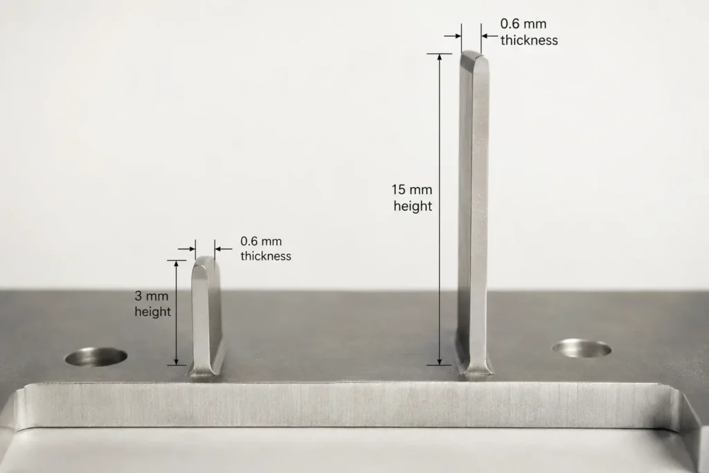
Wall thickness alone doesn’t predict whether a feature machines cleanly. A 0.6 mm wall that’s 3 mm tall and a 0.6 mm wall that’s 15 mm tall are different design problems, even though the thickness callout is identical.
Height-to-thickness ratio is a DFM screening guideline used to flag walls that may need extra process attention, not a defined CNC industry standard. Different manufacturers may use different screening ratios depending on wall support, unsupported length, material, tooling, workholding, and tolerance, rather than working from one agreed number.
Support condition matters more than the ratio itself. A free-standing wall with one unsupported edge deflects far more than a wall supported at both ends, and a wall tied into surrounding geometry, such as a boss, flange, or rib, behaves closer to the supported case even at a similar apparent height. As wall height increases relative to thickness, the wall becomes progressively more sensitive to cutting force, vibration, and deflection, which is why the ratio is used as a screening flag rather than a pass/fail number.
What Affects Achievable Wall Thickness
A CNC machining manufacturer such as ZH Prototyping typically reviews wall thickness together with wall height, tool access, workholding, and tolerance rather than treating thickness as an isolated dimension.
Material stiffness and machinability
Aluminum’s lower cutting forces and higher stiffness-to-weight ratio let it hold thinner walls than stainless steel or titanium at the same geometry. Stainless and titanium need higher cutting forces to shear the material, which pushes harder on a thin section and increases the risk of deflection and heat buildup at the same wall height. Stainless also work-hardens under cutting load, so a tool that rubs instead of shearing cleanly on a thin, flexible wall can drive cutting forces up further rather than staying constant.
Workholding and support
A wall machined while still tied into the surrounding stock is far more stable than the same wall isolated late in the process. Sequencing operations so thin features stay supported as long as possible, and adding sacrificial webs that get removed last, both reduce distortion compared to machining the thin section first.
Tool overhang and pocket depth
A deep pocket forces a longer tool reach, and a longer tool flexes more under the same cutting load. This raises vibration and reduces the achievable wall thickness at the bottom of a deep cavity compared to a shallow one, even in the same material.
Wall geometry and unsupported length
A short wall supported at both ends resists bending far better than a long, free-standing wall of the same thickness. Curves and jogs in a wall’s path add stiffness the same way a corrugated sheet resists bending better than a flat one, which is why curved thin walls often machine cleaner than straight ones at the same thickness.
Tolerance requirements
A loose tolerance gives the wall room to move slightly during and after machining without failing inspection. A tight tolerance on a thin wall usually means slower cuts, more inspection steps, and in some cases a thicker wall than the geometry would otherwise require just to hold the callout.
Using Ribs to Reinforce Thin Walls
A rib lets a design keep a thin outer wall while adding stiffness locally, instead of thickening the whole wall and adding weight and material removal time everywhere.
Rib thickness around 50-60% of the wall it reinforces is a possible starting proportion rather than a universal CNC machining rule. Rib proportions used in die casting shouldn’t automatically be treated as CNC machining rules, because a machined rib is governed more by stiffness, cutter access, workholding, machining sequence, and material removal than by the mold-driven constraints that shape a cast rib.
A rib tied into solid material or a second wall at both ends resists vibration better than a rib that dead-ends in open space. A floating rib with one free end behaves like a small cantilevered wall and can chatter on its own, which sometimes shows up as a poor finish on an otherwise acceptable wall.
Ribs help most when the problem is stiffness against bending, not when the wall is failing from clamping distortion, residual stress movement, or poor workholding. Adding a rib to a wall that’s moving because of fixture pressure won’t fix the root cause.
Design Best Practices for Wall Thickness
Keep wall thickness reasonably consistent across a part. Abrupt changes in section thickness create areas with very different stiffness, and as surrounding material is removed, the thinner section is more sensitive to cutting force and residual stress redistribution, which can make dimensional control less predictable.
Avoid abrupt thickness changes at a single feature edge. A tapered or radiused transition gives the tool a gradual path instead of a step, which reduces the chance of chatter right at the change in section.
Reduce unsupported wall height where the design allows it. Splitting a tall thin wall into two shorter sections with a rib or a shelf between them often machines more reliably than one continuous tall wall at the same thickness.
Use generous internal radii instead of sharp corners. A larger radius allows a bigger, more rigid end mill instead of a long-reach small-diameter tool, which keeps cutter engagement more stable, improves access in deep pockets, and generally cuts machining time compared with clearing a tight inside corner.
Add local support only where the wall actually needs it. Reinforcing every thin feature by default adds material and cycle time without addressing the specific walls that are actually at risk.
Avoid tight tolerances on thin walls unless the application requires them. A general tolerance on a non-critical thin wall gives the process room to work; a tight tolerance in the same location usually means slower cuts and more inspection for a feature that may not need the precision.
How Wall Thickness Affects Cost and Lead Time
Thin walls add cost through the machining process, not through the material itself. Lighter cuts mean more passes to remove the same volume of material, which extends cycle time directly.
Workholding gets more involved. A thin-wall part often needs a dedicated fixture, extra support during roughing, or a specific operation sequence to keep the feature supported until late in the process, and building that into a process plan takes engineering time before the first part is cut.
Inspection tends to grow with wall thickness risk. A wall close to the practical limit is more likely to need dimensional checks at multiple points along its height, rather than a single measurement, to confirm it didn’t taper or bow.
Scrap risk is the least predictable cost driver. A wall that machines fine on the first few parts can still fail intermittently across a production run if fixture wear, tool wear, or material lot variation shifts the balance, and catching that requires in-process monitoring rather than a one-time check.
Making every wall thicker isn’t automatically the cheaper option. Extra thickness means more stock, more material removal, and more roughing time across the whole feature, which adds cycle time in a different way than a thin wall does. The most economical wall thickness is generally the thinnest one that machines reliably without unnecessary process complexity, not the thickest one available.
CNC Machining Wall Thickness at ZH Prototyping
A drawing review before production can identify which walls sit close to the practical limit for the selected material and where wall height, unsupported span, cutter access, fixture access, or tolerance may introduce unnecessary machining risk.
Our DFM review considers material, wall geometry, pocket depth, tool reach, workholding, tolerance, and production quantity together rather than checking wall thickness against one fixed number.
Where a thin-wall feature is likely to create instability, the review may recommend increasing wall thickness, reducing unsupported height, adding local support, opening tool access, or relaxing a non-critical tolerance before production begins.
FAQ
A feasible minimum for aluminum is around 0.5 mm under favorable conditions: short wall height, support on multiple sides, and a controlled machining process. For general design purposes, 0.8 mm is a more reliable starting point that holds up across a wider range of wall heights and tolerances without added process development. The practical limit for a specific part depends more on height-to-thickness ratio and support than on the material spec alone.
Machining shops have cut aluminum walls thinner than 0.5 mm under tightly controlled conditions, but that’s a process-specific capability, not a general design target. Wall height, unsupported length, tolerance, and workholding all move the achievable thickness for a given part. A wall thickness that works in one geometry can be unreliable in another even in the same material.
Not always. A rib helps when a wall is failing from lack of bending stiffness, typically visible as deflection or chatter during cutting. It won’t fix a wall that’s moving because of clamping distortion or residual stress release, since those come from a different mechanism. Whether a rib is the right fix depends on which failure mode is actually occurring.