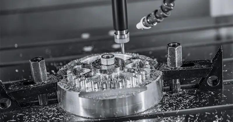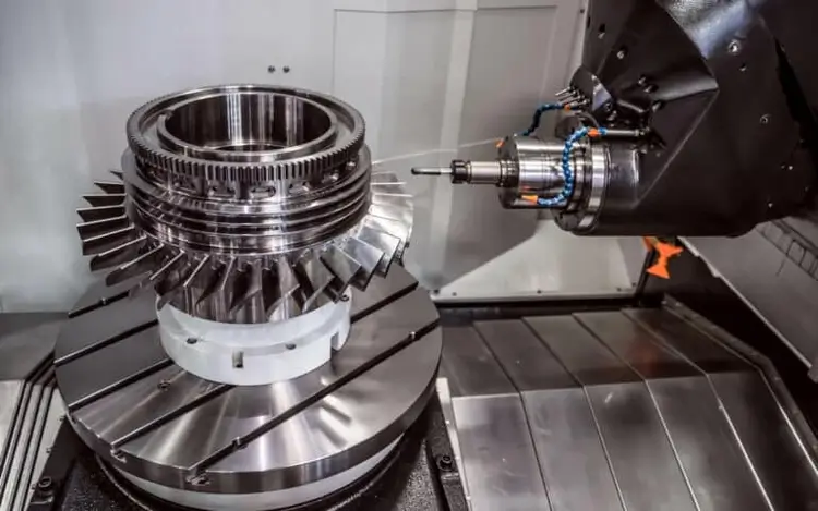

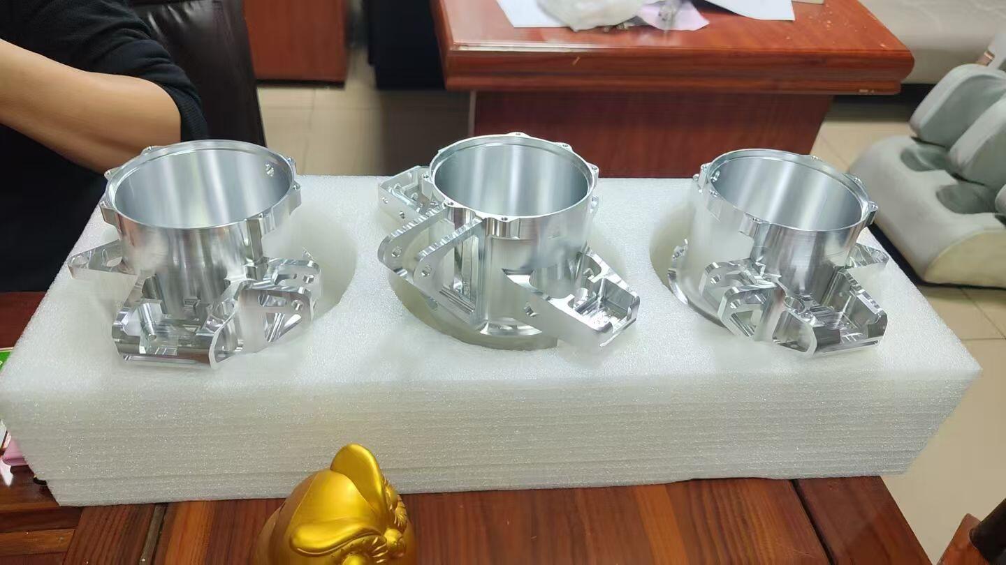
Understanding the CNC machining process helps engineers and product developers make better decisions when selecting materials, optimizing part designs, and choosing the right manufacturing approach. This guide explains each stage of CNC machining, from initial design preparation to the production of finished precision parts.
What Is the CNC Machining Process?
The CNC machining process is a subtractive manufacturing method that uses computer-controlled machines to remove material from a metal workpiece and create components based on a CAD model. The process starts with a digital design and follows programmed machining operations to achieve the required geometry, dimensions, and surface specifications.
Depending on part requirements, manufacturers may use different CNC machining methods, including CNC milling, CNC turning, and multi-axis machining. A professional custom CNC machining service integrates engineering preparation, machine setup, material selection, machining operations, and quality inspection to help ensure finished parts meet specified requirements.
Step-by-Step CNC Machining Process
Turning a CAD design into a finished CNC machined part requires a structured manufacturing workflow. Each stage, from initial design submission and engineering analysis to machining, inspection, and final delivery, plays a specific role in achieving the required part accuracy and performance.
The following sections explain the complete CNC machining process and how manufacturers transform digital designs into precision metal components.
Step 1: CAD File Submission
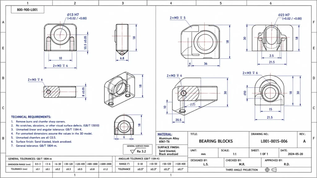
The workflow begins with complete customer-provided part documentation. A full design package includes 3D model files in universal formats (STEP, IGES, X_T) and detailed 2D engineering drawings, which complement 3D geometry with critical manufacturing data.
Customers need to specify material grade, production quantity, dimensional tolerances, surface finish standards, thread details, and special certification or inspection requirements. Unlike 3D models, 2D drawings define enforceable tolerances, key dimensions, and technical notes that govern final part quality.
Step 2: DFM Analysis
After receiving design documents, engineers conduct Design for Manufacturability (DFM) analysis to assess whether the part can be efficiently and consistently produced via CNC machining.
The review evaluates core factors: part geometry, tool accessibility, minimum wall thickness, internal radii, cavity depth, and tolerance feasibility. It identifies potential production risks such as limited tool reach, redundant operations, and overcomplicated designs before mass production.
Our team proposes reasonable design optimizations to improve manufacturability without altering core design intent. This upfront check eliminates costly production errors and delivery delays, laying a practical foundation for subsequent processing.
Step 3: Process Planning
Following DFM confirmation, engineers formulate a targeted machining strategy based on part structure, material properties, tolerance requirements, and production goals. This stage defines the complete manufacturing scheme prior to CNC programming.
Engineers confirm optimal machining methods, equipment selection, processing sequence, fixturing solutions, and setup times. For complex parts, we thoroughly evaluate multi-axis processing demands, custom fixture design, and tool accessibility to ensure stable, repeatable production.
A standardized process plan guides accurate CNC programming and ensures every machining step follows an efficient, controlled workflow.
Step 4: CNC Programming
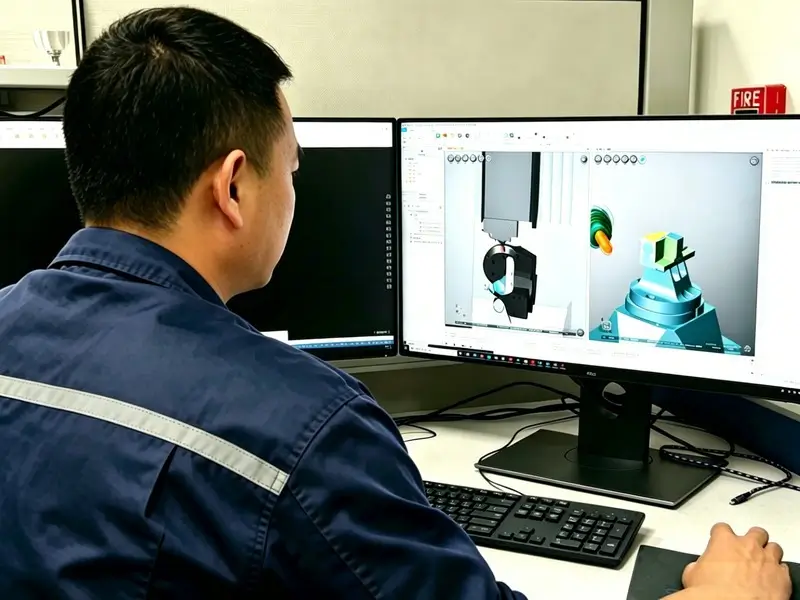
Professional programmers convert verified CAD files and process plans into executable machine instructions via advanced CAM software. The team designs precise toolpaths, selects matched cutting tools, sets rational cutting parameters, and generates formal CNC programs.
Programming covers the full processing sequence: roughing, semi-finishing, and finishing. For complex components, toolpath simulation and collision detection are performed to validate program safety and accuracy before formal production.
Finalized programs deliver precise machine motion and cutting commands, enabling equipment to produce parts that meet dimensional and technical standards.
Step 5: Material Preparation
Raw materials are prepared strictly per part technical specifications. Selecting qualified material grades and standardizing blank sizes is essential to guarantee parts’ mechanical performance and dimensional stability.
Our production team verifies material type, grade, and surface condition before cutting raw stocks into standard CNC blanks. We support diverse materials, including aluminum alloy, stainless steel, carbon steel, brass, copper, titanium, and other specialty alloys.
Standardized material preparation avoids common production issues such as material mismatch, insufficient machining allowance, and defective raw materials.
Step 6: CNC Machine Setup
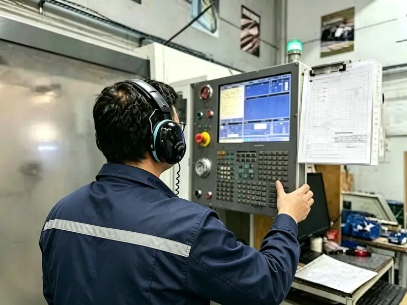
Before production, operators configure CNC equipment per approved process plans to achieve accurate positioning, reliable tooling, and stable machining conditions.
The setup process includes fixture installation, workpiece clamping, program loading, work offset calibration, tool installation, and tool offset adjustment. For high-precision or complex parts, multi-position fixturing and multi-axis alignment are applied to minimize positioning errors.
Precise machine setup ensures consistent machining accuracy and stable operational status for formal processing.
Step 7: CNC Machining Operations
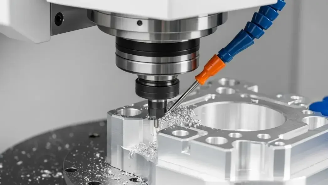
Formal machining runs according to programmed toolpaths and standardized process plans. Cutting tools remove excess workpiece material via controlled movement to shape qualified part geometry.
The process is divided into three core stages: roughing removes most redundant material with reserved machining allowance; semi-finishing optimizes part contours and unifies processing conditions; finishing achieves precise dimensions, tight tolerances, and qualified surface finishes.
Common operations include milling, turning, drilling, tapping, threading, and boring. Multi-axis machining is adopted for complex structural features to reduce repeated setups and maintain dimensional accuracy.
Step 8: Quality Inspection
All machined parts undergo strict dimensional inspection to verify compliance with engineering drawings. Inspectors focus on critical dimensions, tolerance accuracy, surface quality, and overall part integrity.
Quality teams use precision devices including coordinate measuring machines (CMM), micrometers, calipers, and height gauges for comprehensive testing. High-precision parts adopt customized inspection schemes based on application requirements.
Inspection results are recorded in formal reports such as First Article Inspection (FAI) documents, ensuring only qualified parts proceed to subsequent procedures.
Step 9: Surface Finishing
Qualified machined parts receive targeted surface treatments to meet functional and aesthetic demands. Surface finishing effectively improves corrosion resistance, wear resistance, surface smoothness, and visual performance.
Common treatments include aluminum anodizing, stainless steel passivation, powder coating, electroplating, polishing, and brushing. Finishing solutions are customized based on material type, working environment, and end-use requirements.
Parts are thoroughly cleaned before treatment to ensure coating adhesion and uniform finishing effects, followed by targeted quality checks after processing.
Step 10: Final Inspection
A full final inspection is conducted after surface finishing and secondary processing before shipment. This step eliminates defects introduced during surface treatment and reconfirms compliance with all design standards.
Inspectors recheck key indicators including dimensional accuracy, surface finish quality, thread integrity, and overall appearance against original drawings. All results are archived completely for full product traceability.
Only parts passing final inspection are approved for packaging and delivery.
Step 11: Packaging
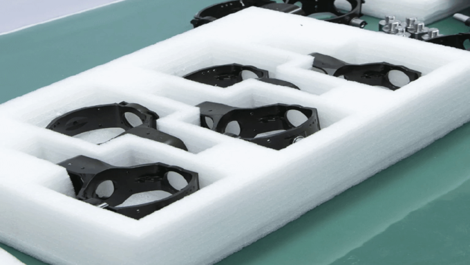
Qualified parts are professionally packaged to prevent scratches, deformation, contamination, and corrosion during transportation. All residual machining debris and surface contaminants are cleaned thoroughly before packaging.
We adopt customized protection measures such as rust prevention treatment and protective films based on part size, shape, surface finish, and shipping demands. Standardized packaging ensures intact part condition upon arrival.
Step 12: Delivery
Finished parts are shipped per customer’s delivery schedules. We select optimal logistics solutions based on destination, order quantity, and lead time requirements, and prepare complete shipping and export documents for domestic and international orders.
Tracking information is provided after shipment dispatch for customers to monitor transportation progress. The entire CNC machining workflow is completed when precision parts arrive safely for assembly and end application.
How ZH Precision Supports Your CNC Machining Projects
ZH Precision offers full-cycle CNC machining support covering engineering evaluation, professional DFM analysis, precision manufacturing, strict quality inspection, custom surface finishing, and reliable final delivery. Our seasoned engineering team assists clients in optimizing part designs, selecting feasible machining strategies, and stabilizing overall production quality.
Equipped with advanced CNC milling, turning, and multi-axis machining capabilities, we provide custom CNC machining services for high-precision metal components in a wide range of materials, with tight dimensional tolerance control and reliable lead times. Whether for rapid prototyping or batch production, ZH Precision delivers customized manufacturing solutions to meet diverse industrial application requirements.
Conclusion
The CNC machining process involves a series of carefully controlled steps, from CAD file review and engineering planning to machining, inspection, finishing, and delivery. Each stage plays an important role in determining the final part’s accuracy, quality, and performance.
By following a structured CNC machining workflow, manufacturers can ensure consistent production results, reduce potential manufacturing issues, and produce precision components that meet engineering requirements. Understanding this complete process helps engineers and product developers make better decisions when designing parts and selecting the right manufacturing approach.
FAQ
The CNC machining lead time depends on part complexity, material, quantity, machining requirements, and finishing processes. Simple components may be completed within a few days, while complex parts requiring multiple operations, inspection, or surface treatments may require additional processing time.
A complete CNC machining project typically requires 3D CAD files and 2D engineering drawings. CAD models define part geometry, while drawings provide critical information such as dimensions, tolerances, surface finishes, threads, and special requirements.
CNC machining can achieve tight dimensional tolerances depending on part design, material, machine capability, and inspection methods. Standard tolerances are commonly achievable for many applications, while precision components may require tighter control through optimized machining processes and advanced measurement equipment.
CNC machining supports a wide range of engineering metals, including aluminum alloys, stainless steel, carbon steel, brass, copper, titanium, and other specialty materials. Material selection depends on factors such as strength, weight, corrosion resistance, machinability, and application requirements.
DFM (Design for Manufacturability) helps identify potential machining challenges before production begins. By reviewing part geometry, tolerances, tooling accessibility, and machining requirements early, engineers can optimize designs, reduce unnecessary processing steps, and improve manufacturing efficiency.